
What are HT12E and HT12D ICs? Pin Diagram, Circuit and Working
Advertisement
HT12E is a CMOS encoder while HT12D is its companion decoder used in RF and infrared remote control systems. Together they enable reliable wireless transmission of address and data bits for home automation, security systems, and remote switching applications.
Key features of HT12E and HT12A ICs
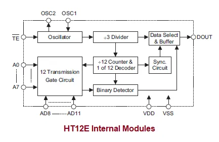
The HT12E and HT12A are CMOS-based encoders designed for remote control applications. They encode 12 bits of information (typically 8 address bits and 4 data bits) into a serial stream that can be transmitted via RF (Radio Frequency) or IR (Infrared).
- Operating Voltage: 2.4V to 12V (HT12E) / 2.4V to 5V (HT12A).
- Low Power Consumption: Low standby current (0.1µA at 5V), making them ideal for battery-operated remotes.
- High Noise Immunity: Utilizes robust CMOS technology.
- Built-in Oscillator: Requires only a single 5% external resistor.
- Trigger Types: The HT12E uses a Transmission Enable (TE) trigger, while the HT12A uses a DATA trigger and includes a built-in 38kHz carrier for IR transmission.
HT12A / HT12E (2^12 Series Encoders) Pin Diagram
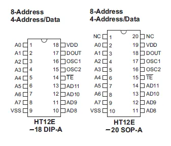
| Pin Name | I/O | Description |
|---|---|---|
| A0~A7 | I | Input pins for address A0~A7 setting. These pins can be externally set to VSS or left open. |
| AD8~AD11 | I | Input pins for address/data AD8~AD11 setting (HT12E). These pins can be externally set to VSS or left open. |
| D8~D11 | I | Input pins for data D8~D11 setting and transmission enable, active low (HT12A). These pins should be externally set to VSS or left open. |
| DOUT | O | Encoder data serial transmission output. |
| L/M | I | Latch/Momentary transmission format selection pin: Latch (Floating or VDD), Momentary (VSS). |
| TE | I | Transmission enable, active low (HT12E). |
| OSC1 | I | Oscillator 1 input pin. |
| OSC2 | O | Oscillator 1 output pin. |
| X1 | I | 455kHz resonator oscillator input (HT12A). |
| X2 | O | 455kHz resonator oscillator output (HT12A). |
| VSS | I | Negative power supply, ground. |
| VDD | I | Positive power supply. |
Key features of HT12D / HT12F (2^12 Series Decoders)
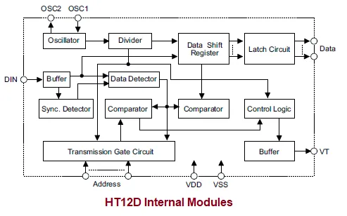
Designed to pair perfectly with the HT12E/HT12A encoders, these decoders receive serial data, compare it to their local address settings, and output the data if the addresses match.
- Operating Voltage: 2.4V to 12V.
- Error Checking: The decoder checks the received code three consecutive times before validating it - to prevent false triggers.
- Output Types: The HT12D provides 4 latched data output bits (maintains state until new data arrives), whereas the HT12F provides momentary output via the VT pin (12 address bits, 0 data).
- Valid Transmission (VT): An output pin that goes HIGH when a valid, matching signal is successfully decoded.
HT12D / HT12F (2^12 Series Decoders)
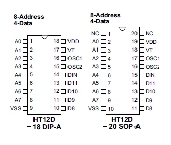
| Pin Name | I/O | Description |
|---|---|---|
| A0~A11 (HT12F) | I | Input pins for address A0~A11 setting. These pins can be externally set to VSS or left open. |
| A0~A7 (HT12D) | I | Input pins for address A0~A7 setting. These pins can be externally set to VSS or left open. |
| D8~D11 (HT12D) | O | Output data pins, power-on state is low. |
| DIN | I | Serial data input pin. |
| VT | O | Valid transmission, active high. |
| OSC1 | I | Oscillator input pin. |
| OSC2 | O | Oscillator output pin. |
| VSS | — | Negative power supply, ground. |
| VDD | — | Positive power supply. |
Example Use Cases
DIY Garage Door Opener Remote: You can build a handheld remote powered by a 3V coin cell using the HT12E. Using an 8-position DIP switch connected to pins A0-A7, you can set a unique address. When a push-button (connected to TE and data pins) is pressed, the IC wakes up, encodes the DIP switch address and button data, and sends the serial data to a 433MHz RF transmitter module to open the garage.
Remote Light Controller: In the receiver box mounted near a lighting fixture, an HT12D is paired with a 433MHz RF receiver. When the HT12D receives a signal matching its hard-wired address on A0-A7, it pulls the specific data pin (D8) HIGH. This latched output drives an NPN transistor, which clicks a relay closed to turn on the room lights. The VT pin can be wired to an LED to visually confirm a signal was received.
Summary
HT12E and HT12D simplify wireless remote control system design using encoder-decoder communication.
Continue Learning Forward Error Correction (FEC) & Channel Coding
- Forward Error Correction: Advantages & Disadvantages
- Convolutional Encoder Example
- Turbo Encoder Basics
- CIRC Encoding vs Decoding
- Differential Encoder/Decoder Explained
Explore AI & Audio Coders
- Rotary Encoder: Basics and Types
- Understanding Vocoding and Vocoders
- Autoencoder Function in 6G Networks
Explore Data Encoding Techniques
- Encoding vs Modulation: Understanding the Difference
- Manchester vs Differential Manchester Encoding
- 4B/5B Encoding: Advantages & Disadvantages
- 8B/10B Encoding: Advantages & Disadvantages
- 64B/66B vs 8B/10B Encoding Comparison
- HDB3 Encoding: Advantages & Disadvantages
- MLT-3 Encoding: Advantages & Disadvantages
- R8ZS Encoding: Advantages & Disadvantages
- RZ, NRZ, CRZ, CSRZ Line Encoding Comparison