
AD8362 RMS Detector IC Pin Diagram, Circuit and Applications
Advertisement
The AD8362 is a true RMS detector IC that accurately measures the root mean square value of RF and low-frequency signals independent of waveform shape. It is suitable for signal conditioning, power measurement, instrumentation, and communication systems. This guide covers the AD8362 pin diagram, working principle, circuit implementation, features, and applications.
Key features of AD8362
- Broad Frequency Range: Operates accurately from exceptionally low frequencies (50 Hz) all the way up to 3.8 GHz.
- Wide Dynamic Range: Provides over 65 dB of measurement range, accepting input power levels from −52 dBm to +8 dBm (referenced to 50 Ω).
- Modulation Independence: True RMS detection ensures that the measurement remains accurate regardless of the modulation scheme (e.g., CDMA, W-CDMA, GSM, TDMA, QAM, and OFDM).
- Linear in dB Output: Outputs a highly stable, decibel-scaled voltage with a standard slope of 50 mV/dB (which can be adjusted externally) and a tight law conformance error of just 0.5 dB.
- Excellent Stability: Designed to maintain highly stable performance across varying supply voltages and temperature shifts (−40°C to +85°C).
- Low Power Consumption: Operates on a single 5 V supply drawing approximately 24 mA. It features a power down pin that reduces power consumption to just 1.3 mW (230 µA current draw) when disabled.
- Dual Operating Modes: Can be wired for direct RF signal measurement or configured as an analog controller for closed-loop systems.
AD8362 Pin Diagram
Here’s a look at the AD8362 pin diagram:
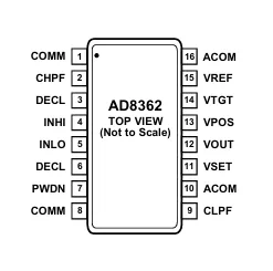
| Pin No. | Pin Name | Type | Function |
|---|---|---|---|
| 1 | COMM | Ground | Common ground connection. Connect to the PCB ground using a low-impedance path. |
| 2 | CHPF | Analog | High-pass filter capacitor connection. An external capacitor connected to ground determines the low-frequency cutoff of the input high-pass filter. |
| 3 | DECL | Analog | Decoupling terminal for the INHI input stage. Connect to ground through a large bypass capacitor. |
| 4 | INHI | RF Input | Positive (high) differential RF input. Can also be driven in single-ended mode. |
| 5 | INLO | RF Input | Negative (low) differential RF input. Forms the differential input pair with INHI. |
| 6 | DECL | Analog | Decoupling terminal for the INLO input stage. Connect to ground through a large bypass capacitor. |
| 7 | PWDN | Digital Input | Power-down control input. Logic High places the device in low-power shutdown mode; Logic Low enables normal operation. |
| 8 | COMM | Ground | Common ground connection for the input circuitry. |
| 9 | CLPF | Analog | Loop filter capacitor connection. An external capacitor determines the averaging time constant and output response speed. |
| 10 | ACOM | Ground | Analog ground reference for the output amplifier section. |
| 11 | VSET | Analog Input | Setpoint input. Connect directly to VOUT in measurement mode or apply an external reference in controller mode. |
| 12 | VOUT | Analog Output | RMS detector output voltage. Produces a DC voltage proportional to the logarithm of the RMS input signal power. |
| 13 | VPOS | Power | Positive power supply input. Operates from 4.5 V to 5.5 V. |
| 14 | VTGT | Analog Input | Target/reference input that determines the logarithmic intercept. Normally connected to VREF. |
| 15 | VREF | Output | Precision 1.25 V reference voltage output. Typically connected to VTGT. |
| 16 | ACOM | Ground | Analog ground connection for the output circuitry. |
Example Use Case : AD8362 as Closed Loop Automatic Power Control
While the AD8362 is often used simply to measure an RF signal (Measurement Mode), one of its most powerful applications is in Controller Mode to automatically regulate the output of a Variable Gain Amplifier (VGA) or Power Amplifier (PA).
Applications of AD8362
- Transmitter Power Control: Managing and stabilizing transmission outputs in base stations or mobile hardware.
- Power Amplifier (PA) Linearization: Serving as the feedback mechanism in closed-loop PA control systems.
- Transmitter Signal Strength Indication (TSSI): Accurately tracking outgoing signal power.
- RF Instrumentation: Serving as a precision RMS voltmeter or RF power meter covering a massive 1,000,000:1 power ratio.
Summary
The AD8362 delivers precise RMS measurements across a broad frequency range. It is widely used in RF instrumentation and signal monitoring systems.