
Asynchronous FIFO Verilog Code and Test Bench
By RF Wireless Expert Team
Advertisement
This article provides Verilog code for an Asynchronous FIFO (First-In, First-Out) and its corresponding test bench. We’ll also examine the simulated output.
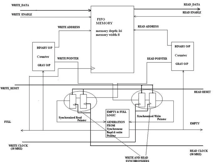
Figure 1: Asynchronous FIFO Design
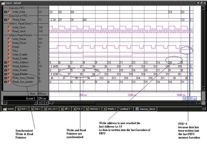
Figure 2: Simulation Output of Asynchronous FIFO
The image above (Figure 2) shows the simulation output of the Asynchronous FIFO design depicted in Figure 1.
Asynchronous FIFO Verilog Code
Here’s the Verilog code for the Asynchronous FIFO:
module tb_top();
  reg wr_clk,rd_clk;
  reg[7:0] data_in;
  wire[7:0] data_out;
  wire rd_empty,wr_full;
  reg reset_w;
  reg reset_r;
  reg write_enable,read_enable;

  top top_1(
    .wr_data(data_in),
    .rd_data(data_out),
    .wr_clk(wr_clk),
    .rd_clk(rd_clk),
    .w_reset(reset_w),
    .r_reset(reset_r),
    .write_enable(write_enable),
    .read_enable(read_enable),
    .empty(rd_empty),
    .full(wr_full)
  );

  initial begin
    #0 data_in=8'h0;
    #50_000 data_in=8'b00000001;  // DATA WHICH IS SUPPLIED
    #80_000 data_in=8'h2;
    #70_000 data_in=8'h3;
    #79_000 data_in=8'h4;
    #80_000 data_in=8'h5;
    #40_000 data_in=8'h6;
    #60_000 data_in=8'h7;
    #50_000 data_in=8'h8;
    #50_000 data_in=8'h9;
    #20_000 data_in=8'h10;
    #70_000 data_in=8'h11;
    #80_000 data_in=8'h12;
    #19_000 data_in=8'h13;
    #10_000 data_in=8'h14;
    #80_000 data_in=8'h15;
  end

  initial begin
    wr_clk=1'b0;
    write_enable=1'b0;
    read_enable=1'b0;
  end

  initial always #50000 wr_clk=~wr_clk; //end

  // READ AND WRITE CLOCK GENERATION
  rd_clk=1'b0;
  initial begin
    always #10000 rd_clk=~rd_clk;
  end

  initial reset_r=1'b0;
  begin
    initial #5000 reset_r=1'b1; //end

    initial reset_w =1'b0;
    initial #5000 reset_w=1'b1;

    initial #5000 write_enable=1'b1;

    initial #50000 read_enable=1'b1;

    initial begin
      #1000000000 $finish;
    end

    initial $monitor( "$time data_out,empty ,full= %d %d %d",data_out,rd_empty,wr_full);
  end
endmodule
Asynchronous FIFO Test Bench
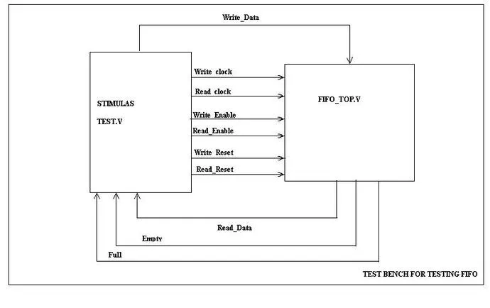
Figure 3: Asynchronous FIFO Test Bench
The image above (Figure 3) illustrates the Asynchronous FIFO Test bench setup.
Following is the pdf which describes all the modules used in this Asynchronous FIFO.
Explore Verilog Logic Gates, Mux & Encoders
- Verilog HDL Code for All Logic Gates
- 2-to-4 Decoder (Verilog HDL Code)
- 4-to-1 Multiplexer and 1-to-4 Demultiplexer (Verilog Code)
- Verilog Code: 1-to-4 Demultiplexer
- 8-to-1 Multiplexer (Verilog HDL Code)
- 8-to-3 Encoder Without Priority (Verilog)
- 8-to-3 Priority Encoder (Verilog)
- 8-to-3 Priority Encoder (Verilog Code)
- 1-Bit and 4-Bit Comparator Design (Verilog)
Explore Verilog Flip-Flops, Counters & Registers
- T, D, SR, JK Flip Flop (Verilog HDL Code)
- D Flip Flop Synchronous Reset (Verilog)
- D Flip Flop Without Reset (Verilog)
- Verilog Code for Binary Up-Down Counter
- Verilog HDL: BCD & Gray Counters
- 4-bit Down Counter (Verilog Code Test Bench)
- 4-bit Binary Asynchronous Reset Counter (Verilog)
- 4-bit Binary Synchronous Reset Counter (Verilog)
- 4-bit BCD Asynchronous Reset Counter (Verilog)
- 4-bit BCD Synchronous Reset Counter (Verilog Code)
- 4-bit Mod-13 Counter (Verilog Code Test Bench)
- Shift Left / Shift Right Register (Verilog)
- Parallel Load Shift Left Register (Verilog Code)
- PRBS Generator (Verilog Code Test Bench)
Explore Verilog Math, Processing & Memory
- Full Adder (Verilog HDL Code)
- Verilog Code: Half Adder, Half Subtractor, Full Subtractor
- 32-Bit ALU (Verilog Code)
- RAM / ROM (Verilog Code)
- Asynchronous FIFO (Verilog Code Test Bench)
- Asynchronous FIFO Design (Verilog Code and Explanation)
- Mealy / Moore Machine (Verilog)
- Low Pass FIR Filter (Verilog Code)
- 4-bit Binary to Gray Counter Converter in Verilog