
T, D, SR, JK Flip-Flop Verilog HDL Code Examples
By RF Wireless Expert Team
Advertisement
This page covers HDL (Hardware Description Language) code in Verilog for T, D, SR, and JK flip-flops.
T Flip-Flop
Symbol
Here’s the symbol and truth table for a T flip-flop:
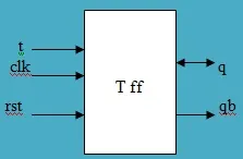
Truth Table
| Rst | T | Clk | q |
|---|---|---|---|
| 1 | 0 | 1 | q |
| 1 | 1 | 1 | qb |
| 1 | X | No positive edge | Previous state |
| 0 | X | X | 0 |
Verilog Code
module tff(t, clk, rst, q, qb);
  input t, clk, rst;
  output q, qb;
  reg q, qb;
  reg temp = 0;

  always @(posedge clk, posedge rst) begin
    if (rst == 0) begin
      if (t == 1) begin
        temp = ~temp;
      end else temp = temp;
    end
    q = temp;
    qb = ~temp;
  end
endmodule
Simulation Result

D Flip-Flop
Symbol
Here’s the symbol and truth table for a D flip-flop:
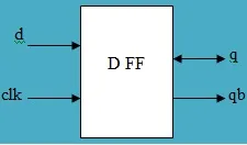
Truth Table
| clk | d | q | qb |
|---|---|---|---|
| X | 1 | 1 | 0 |
| 1 | 1 | 1 | 0 |
| 1 | 0 | 0 | 1 |
Verilog Code
module dff(d, clk, rst, q, qb);
  input d, clk, rst;
  output q, qb;
  reg q, qb;
  reg temp = 0;

  always @(posedge clk, posedge rst) begin
    if (rst == 0)
      temp = d;
    else
      temp = temp;
    q = temp;
    qb = ~temp ;
  end
endmodule
Simulation Result

SR Flip-Flop
Symbol
Following is the symbol and truth table of SR flipflop.
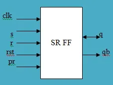
Truth Table
| rst | pr | Clk | s | r | q | qb |
|---|---|---|---|---|---|---|
| 1 | X | X | X | X | 0 | 1 |
| 0 | 1 | X | X | X | 1 | 0 |
| 0 | 0 | 1 | 0 | 0 | Qbprevious | Qbprevious |
| 0 | 0 | 1 | 0 | 1 | 0 | 1 |
| 0 | 0 | 1 | 1 | 0 | 1 | 0 |
| 0 | 0 | 1 | 1 | 1 | 1 | 1 |
Verilog Code
module srff(s, r, clk, rst, q, qb);
  input s, r, clk, rst;
  output q, qb;
  reg q, qb;
  reg [1:0] sr;

  always @(posedge clk, posedge rst) begin
    sr = {s, r};
    if (rst == 0) begin
      case (sr)
        2'd1: q = 1'b0;
        2'd2: q = 1'b1;
        2'd3: q = 1'b1;
        default: begin end
      endcase
    end else begin
      q = 1'b0;
    end
    qb = ~q;
  end
endmodule
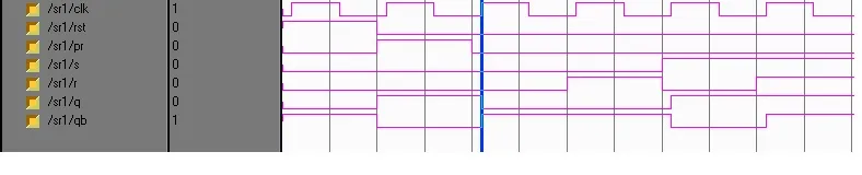
Simulation Result
JK Flip-Flop
Symbol
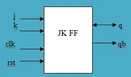
Here’s the symbol and truth table for a JK flip-flop:
Truth Table
| Rst | Clk | J | K | Q | Qb |
|---|---|---|---|---|---|
| 1 | 1 | 0 | 0 | Previous state | |
| 1 | 1 | 0 | 1 | 0 | 1 |
| 1 | 1 | 1 | 0 | 1 | 0 |
| 1 | 1 | 1 | 1 | Qb | Q |
| 1 | No +ve edge | - | - | Previous state | |
| 0 | - | - | - | 0 | 1 |
Verilog Code
module jkff(j, k, clk, rst, q, qb);
  input j, k, clk, rst;
  output q, qb;
  reg q, qb;
  reg [1:0] jk;

  always @(posedge clk, posedge rst) begin
    jk = {j, k};
    if (rst == 0) begin
      case (jk)
        2'd1: q = 1'b0;
        2'd2: q = 1'b1;
        2'd3: q = ~q;
        default: begin end
      endcase
    end else
      q = 1'b0;
    qb = ~q;
  end
endmodule
Simulation Result

Explore Verilog Logic Gates, Mux & Encoders
- Verilog HDL Code for All Logic Gates
- 2-to-4 Decoder (Verilog HDL Code)
- 4-to-1 Multiplexer and 1-to-4 Demultiplexer (Verilog Code)
- Verilog Code: 1-to-4 Demultiplexer
- 8-to-1 Multiplexer (Verilog HDL Code)
- 8-to-3 Encoder Without Priority (Verilog)
- 8-to-3 Priority Encoder (Verilog)
- 8-to-3 Priority Encoder (Verilog Code)
- 1-Bit and 4-Bit Comparator Design (Verilog)
Explore Verilog Flip-Flops, Counters & Registers
- T, D, SR, JK Flip Flop (Verilog HDL Code)
- D Flip Flop Synchronous Reset (Verilog)
- D Flip Flop Without Reset (Verilog)
- Verilog Code for Binary Up-Down Counter
- Verilog HDL: BCD & Gray Counters
- 4-bit Down Counter (Verilog Code Test Bench)
- 4-bit Binary Asynchronous Reset Counter (Verilog)
- 4-bit Binary Synchronous Reset Counter (Verilog)
- 4-bit BCD Asynchronous Reset Counter (Verilog)
- 4-bit BCD Synchronous Reset Counter (Verilog Code)
- 4-bit Mod-13 Counter (Verilog Code Test Bench)
- Shift Left / Shift Right Register (Verilog)
- Parallel Load Shift Left Register (Verilog Code)
- PRBS Generator (Verilog Code Test Bench)
Explore Verilog Math, Processing & Memory
- Full Adder (Verilog HDL Code)
- Verilog Code: Half Adder, Half Subtractor, Full Subtractor
- 32-Bit ALU (Verilog Code)
- RAM / ROM (Verilog Code)
- Asynchronous FIFO (Verilog Code Test Bench)
- Asynchronous FIFO Design (Verilog Code and Explanation)
- Mealy / Moore Machine (Verilog)
- Low Pass FIR Filter (Verilog Code)
- 4-bit Binary to Gray Counter Converter in Verilog