4-Bit Binary to Gray Counter Converter in Verilog
Advertisement
This article presents a Verilog implementation of a 4-bit binary to Gray code counter converter.
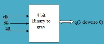
Symbol and Truth Table
Here’s the symbol and truth table for the 4-bit binary to Gray counter converter:
Truth Table:
| Rst | Clk | En | B3 | B2 | B1 | B0 | G3 | G2 | G1 | G0 |
|---|---|---|---|---|---|---|---|---|---|---|
| 1 | X | 0 | 0 | 0 | 0 | 0 | 0 | 0 | 0 | 0 |
| 0 | 0 | 1 | 0 | 0 | 0 | 1 | 0 | 0 | 0 | 1 |
| 0 | 1 | 1 | 0 | 0 | 1 | 0 | 0 | 0 | 1 | 1 |
| 0 | 0 | 1 | 0 | 0 | 1 | 1 | 0 | 0 | 1 | 0 |
| 0 | 1 | 1 | 0 | 1 | 0 | 0 | 0 | 1 | 1 | 0 |
| 0 | 0 | 1 | 0 | 1 | 0 | 1 | 0 | 1 | 1 | 1 |
| 0 | 1 | 1 | 0 | 1 | 1 | 0 | 0 | 1 | 0 | 1 |
| 0 | 0 | 1 | 0 | 1 | 1 | 1 | 0 | 1 | 0 | 0 |
| 0 | 1 | 1 | 1 | 0 | 0 | 0 | 1 | 1 | 0 | 0 |
| 0 | 0 | 1 | 1 | 0 | 0 | 1 | 1 | 1 | 0 | 1 |
| 0 | 1 | 1 | 1 | 0 | 1 | 0 | 1 | 1 | 1 | 1 |
| 0 | 0 | 1 | 1 | 0 | 1 | 1 | 1 | 1 | 1 | 0 |
| 0 | 1 | 1 | 1 | 1 | 0 | 0 | 1 | 0 | 1 | 0 |
Verilog Code
Here’s the Verilog code for the 4-bit binary to Gray code converter:
module b2g(b,g);
  input [3:0] b;
  output [3:0] g;

  xor (g[0],b[0],b[1]),
      (g[1],b[1],b[2]),
      (g[2],b[2],b[3]);

  assign g[3]=b[3];
endmodule
This Verilog module, b2g, takes a 4-bit binary input b and outputs a 4-bit Gray code g. The Gray code bits are generated by XORing adjacent bits of the binary input, with the most significant bit (MSB) remaining the same.
Simulation Result
The following image shows a simulation result for the Verilog code:
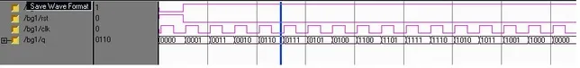
This result verifies the functionality of the designed Verilog code.