
Verilog Code for Half Adder, Half Subtractor, and Full Subtractor
By RF Wireless Expert Team
Advertisement
This page provides Verilog HDL code for a half adder, half subtractor, and full subtractor. Let’s dive into the details.
Half Adder
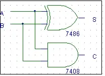
The half adder truth table and schematic (Fig. 1) are shown below.
The boolean expressions are:
- Sum (S) = A XOR B ()
- Carry (C) = A AND B ()
Half Adder Truth Table
| Input A | Input B | Output S | Output C |
|---|---|---|---|
| 0 | 0 | 0 | 0 |
| 0 | 1 | 1 | 0 |
| 1 | 0 | 1 | 0 |
| 1 | 1 | 0 | 1 |
Half Adder Schematic
Half Adder Verilog Code
module ha ( a, b, s, c);
  input a, b;
  output s, c;

  assign s = a ^ b;
  assign c = a & b;
endmodule
Half Subtractor
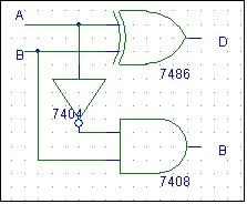
The half subtractor truth table and schematic (Fig. 2) are provided below.
The boolean expressions are:
- Difference (D) = A XOR B ()
- Borrow (Br) = NOT A AND B ()
Half Subtractor Truth Table
| Input A | Input B | Output D | Output Br |
|---|---|---|---|
| 0 | 0 | 0 | 0 |
| 0 | 1 | 1 | 1 |
| 1 | 0 | 1 | 0 |
| 1 | 1 | 0 | 0 |
Half Subtractor Schematic
Half Subtractor Verilog Code
module hs ( a, b, d, br);
  input a, b;
  output d, br;

  assign d = a ^ b;
  assign br = ~a & b;
endmodule
Full Subtractor
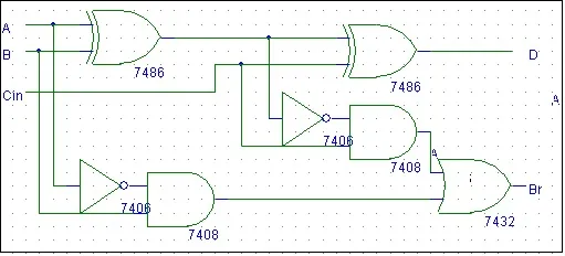
The full subtractor truth table and schematic (Fig. 3) are mentioned below.
The boolean expressions are:
- Difference (D) = A XOR B XOR Cin ()
- Borrow (Br) = (NOT A AND B) OR (B AND Cin) OR (NOT A AND Cin) ()
Full Subtractor Truth Table
| Input A | Input B | Input Cin | Output D | Output Br |
|---|---|---|---|---|
| 0 | 0 | 0 | 0 | 0 |
| 0 | 0 | 1 | 1 | 1 |
| 0 | 1 | 0 | 1 | 1 |
| 0 | 1 | 1 | 0 | 1 |
| 1 | 0 | 0 | 1 | 0 |
| 1 | 0 | 1 | 0 | 0 |
| 1 | 1 | 0 | 0 | 0 |
| 1 | 1 | 1 | 1 | 1 |
Full Subtractor Schematic
Full Subtractor Verilog Code
module fs ( a, b, c, d, br);
  input a, b, c;
  output d, br;

  assign d = a ^ b ^ c;
  assign br=(( ~a)& (b ^ c)) | (b & c);
endmodule
Explore Verilog Logic Gates, Mux & Encoders
- Verilog HDL Code for All Logic Gates
- 2-to-4 Decoder (Verilog HDL Code)
- 4-to-1 Multiplexer and 1-to-4 Demultiplexer (Verilog Code)
- Verilog Code: 1-to-4 Demultiplexer
- 8-to-1 Multiplexer (Verilog HDL Code)
- 8-to-3 Encoder Without Priority (Verilog)
- 8-to-3 Priority Encoder (Verilog)
- 8-to-3 Priority Encoder (Verilog Code)
- 1-Bit and 4-Bit Comparator Design (Verilog)
Explore Verilog Flip-Flops, Counters & Registers
- T, D, SR, JK Flip Flop (Verilog HDL Code)
- D Flip Flop Synchronous Reset (Verilog)
- D Flip Flop Without Reset (Verilog)
- Verilog Code for Binary Up-Down Counter
- Verilog HDL: BCD & Gray Counters
- 4-bit Down Counter (Verilog Code Test Bench)
- 4-bit Binary Asynchronous Reset Counter (Verilog)
- 4-bit Binary Synchronous Reset Counter (Verilog)
- 4-bit BCD Asynchronous Reset Counter (Verilog)
- 4-bit BCD Synchronous Reset Counter (Verilog Code)
- 4-bit Mod-13 Counter (Verilog Code Test Bench)
- Shift Left / Shift Right Register (Verilog)
- Parallel Load Shift Left Register (Verilog Code)
- PRBS Generator (Verilog Code Test Bench)
Explore Verilog Math, Processing & Memory
- Full Adder (Verilog HDL Code)
- Verilog Code: Half Adder, Half Subtractor, Full Subtractor
- 32-Bit ALU (Verilog Code)
- RAM / ROM (Verilog Code)
- Asynchronous FIFO (Verilog Code Test Bench)
- Asynchronous FIFO Design (Verilog Code and Explanation)
- Mealy / Moore Machine (Verilog)
- Low Pass FIR Filter (Verilog Code)
- 4-bit Binary to Gray Counter Converter in Verilog