
Low Pass FIR Filter Verilog Implementation
Advertisement
Okay, here’s your article converted to Markdown format, incorporating the requirements you specified.
Low Pass FIR Filter Verilog Code
In this implementation, we’re using the same coefficients that were used in the second type of implementation. Specifically, these coefficients are generated from MATLAB, converted into Q-15 format (in hexadecimal representation), and then used in the Verilog code. We’re also using the same input signal of 15 Hz and 100 Hz, converting it into Q-15 format (hexadecimal representation) for use in Verilog.
Verilog Code for Low Pass FIR Filter (Top Module)
module fir_filter(d_out, x, clk, reset, valid);
  output signed[15:0] d_out;
  input signed [15:0] x;
  input clk, reset, valid;

  wire signed[15:0] b[0:50];
  reg[5:0] coeff_add;
  reg signed [31:0] temp0, temp1, temp2, temp3, temp4, temp5, temp6, temp7, temp8,
                      temp9, temp10, temp11, temp12, temp13, temp14, temp15, temp16, temp17, temp18,
                      temp19, temp20, temp21, temp22, temp23, temp24, temp25, temp26, temp27, temp28,
                      temp29, temp30, temp31, temp32, temp33, temp34, temp35, temp36, temp37, temp38,
                      temp39, temp40, temp41, temp42, temp43, temp44, temp45, temp46, temp47, temp48,
                      temp49, temp50;
  reg signed [15:0] y;
  reg signed [15:0] z0, z1, z2, z3, z4, z5, z6, z7, z8, z9, z10, z11, z12, z13, z14, z15,
                      z16, z17, z18, z19, z20, z21, z22, z23, z24, z25, z26, z27, z28, z29, z30, z31, z32, z33, z34,
                      z35, z36, z37, z38, z39, z40, z41, z42, z43, z44, z45, z46, z47, z48, z49, z50;

  assign b[0] = 16'hFFE8;
  assign b[1] = 16'hFF8E;
  assign b[2] = 16'hFFAC;
  assign b[3] = 16'hFFA0;
  assign b[4] = 16'hFFC2;
  assign b[5] = 16'h0002;
  assign b[6] = 16'h005F;
  assign b[7] = 16'h00C6;
  assign b[8] = 16'h0119;
  assign b[9] = 16'h013B;
  assign b[10] = 16'h010F;
  assign b[11] = 16'h0087;
  assign b[12] = 16'hFFAB;
  assign b[13] = 16'hFE9A;
  assign b[14] = 16'hFD8F;
  assign b[15] = 16'hFCD4;
  assign b[16] = 16'hFCB6;
  assign b[17] = 16'hFD76;
  assign b[18] = 16'hFF37;
  assign b[19] = 16'h01F0;
  assign b[20] = 16'h056F;
  assign b[21] = 16'h0952;
  assign b[22] = 16'h0D1E;
  assign b[23] = 16'h104F;
  assign b[24] = 16'h126F;
  assign b[25] = 16'h132E;
  assign b[26] = 16'h126F;
  assign b[27] = 16'h104F;
  assign b[28] = 16'h0D1E;
  assign b[29] = 16'h0952;
  assign b[30] = 16'h056F;
  assign b[31] = 16'h01F0;
  assign b[32] = 16'hFF37;
  assign b[33] = 16'hFD76;
  assign b[34] = 16'hFCB6;
  assign b[35] = 16'hFCD4;
  assign b[36] = 16'hFD8F;
  assign b[37] = 16'hFE9A;
  assign b[38] = 16'hFFAB;
  assign b[39] = 16'h0087;
  assign b[40] = 16'h010F;
  assign b[41] = 16'h013B;
  assign b[42] = 16'h0119;
  assign b[43] = 16'h00C6;
  assign b[44] = 16'h005F;
  assign b[45] = 16'h0002;
  assign b[46] = 16'hFFC2;
  assign b[47] = 16'hFFA0;
  assign b[48] = 16'hFFAC;
  assign b[49] = 16'hFF8E;
  assign b[50] = 16'hFFE8;

  always @(posedge clk) begin
    if (reset)
      coeff_add <= 6'd0;
    else if (coeff_add == 6'd50)
      coeff_add <= 6'd1;
    else if (valid)
      coeff_add <= coeff_add + 1'd1;
  end

  always @(posedge clk) begin
    if (reset) begin
      temp0 <= 16'd0; temp1 <= 16'd0; temp2 <= 16'd0; temp3 <= 16'd0; temp4 <= 16'd0;
      temp5 <= 16'd0; temp6 <= 16'd0; temp7 <= 16'd0; temp8 <= 16'd0; temp9 <= 16'd0;
      temp10 <= 16'd0; temp11 <= 16'd0; temp12 <= 16'd0; temp13 <= 16'd0; temp14 <= 16'd0;
      temp15 <= 16'd0; temp16 <= 16'd0; temp17 <= 16'd0; temp18 <= 16'd0; temp19 <= 16'd0;
      temp20 <= 16'd0; temp21 <= 16'd0; temp22 <= 16'd0; temp23 <= 16'd0; temp24 <= 16'd0;
      temp25 <= 16'd0; temp26 <= 16'd0; temp27 <= 16'd0; temp28 <= 16'd0; temp29 <= 16'd0;
      temp30 <= 16'd0; temp31 <= 16'd0; temp32 <= 16'd0; temp33 <= 16'd0; temp34 <= 16'd0;
      temp35 <= 16'd0; temp36 <= 16'd0; temp37 <= 16'd0; temp38 <= 16'd0; temp39 <= 16'd0;
      temp40 <= 16'd0; temp41 <= 16'd0; temp42 <= 16'd0; temp43 <= 16'd0; temp44 <= 16'd0;
      temp45 <= 16'd0; temp46 <= 16'd0; temp47 <= 16'd0; temp48 <= 16'd0; temp49 <= 16'd0;
      temp50 <= 16'd0;
      y <= 16'd0;
      z0 <= 16'd0; z1 <= 16'd0; z2 <= 16'd0; z3 <= 16'd0; z4 <= 16'd0; z5 <= 16'd0; z6 <= 16'd0;
      z7 <= 16'd0; z8 <= 16'd0; z9 <= 16'd0; z10 <= 16'd0; z11 <= 16'd0; z12 <= 16'd0;
      z13 <= 16'd0; z14 <= 16'd0; z15 <= 16'd0; z16 <= 16'd0; z17 <= 16'd0; z18 <= 16'd0;
      z19 <= 16'd0; z20 <= 16'd0; z21 <= 16'd0; z22 <= 16'd0; z23 <= 16'd0; z24 <= 16'd0;
      z25 <= 16'd0; z26 <= 16'd0; z27 <= 16'd0; z28 <= 16'd0; z29 <= 16'd0; z30 <= 16'd0;
      z31 <= 16'd0; z32 <= 16'd0; z33 <= 16'd0; z34 <= 16'd0; z35 <= 16'd0; z36 <= 16'd0;
      z37 <= 16'd0; z38 <= 16'd0; z39 <= 16'd0; z40 <= 16'd0; z41 <= 16'd0; z42 <= 16'd0;
      z43 <= 16'd0; z44 <= 16'd0; z45 <= 16'd0; z46 <= 16'd0; z47 <= 16'd0; z48 <= 16'd0;
      z49 <= 16'd0; z50 <= 16'd0;
    end else if (valid) begin
      z0 <= x; z1 <= z0; z2 <= z1; z3 <= z2; z4 <= z3; z5 <= z4; z6 <= z5;
      z7 <= z6; z8 <= z7; z9 <= z8; z10 <= z9; z11 <= z10; z12 <= z11;
      z13 <= z12; z14 <= z13; z15 <= z14; z16 <= z15; z17 <= z16; z18 <= z17;
      z19 <= z18; z20 <= z19; z21 <= z20; z22 <= z21; z23 <= z22; z24 <= z23;
      z25 <= z24; z26 <= z25; z27 <= z26; z28 <= z27; z29 <= z28; z30 <= z29;
      z31 <= z30; z32 <= z31; z33 <= z32; z34 <= z33; z35 <= z34; z36 <= z35;
      z37 <= z36; z38 <= z37; z39 <= z38; z40 <= z39; z41 <= z40; z42 <= z41;
      z43 <= z42; z44 <= z43; z45 <= z44; z46 <= z45; z47 <= z46; z48 <= z47;
      z49 <= z48; z50 <= z49;

      temp0 <= z0 * b[0]; temp1 <= z1 * b[1]; temp2 <= z2 * b[2]; temp3 <= z3 * b[3]; temp4 <= z4 * b[4];
      temp5 <= z5 * b[5]; temp6 <= z6 * b[6]; temp7 <= z7 * b[7]; temp8 <= z8 * b[8]; temp9 <= z9 * b[9];
      temp10 <= z10 * b[10]; temp11 <= z11 * b[11]; temp12 <= z12 * b[12]; temp13 <= z13 * b[13]; temp14 <= z14 * b[14];
      temp15 <= z15 * b[15]; temp16 <= z16 * b[16]; temp17 <= z17 * b[17]; temp18 <= z18 * b[18]; temp19 <= z19 * b[19];
      temp20 <= z20 * b[20]; temp21 <= z21 * b[21]; temp22 <= z22 * b[22]; temp23 <= z23 * b[23]; temp24 <= z24 * b[24];
      temp25 <= z25 * b[25]; temp26 <= z26 * b[26]; temp27 <= z27 * b[27]; temp28 <= z28 * b[28]; temp29 <= z29 * b[29];
      temp30 <= z30 * b[30]; temp31 <= z31 * b[31]; temp32 <= z32 * b[32]; temp33 <= z33 * b[33]; temp34 <= z34 * b[34];
      temp35 <= z35 * b[35]; temp36 <= z36 * b[36]; temp37 <= z37 * b[37]; temp38 <= z38 * b[38]; temp39 <= z39 * b[39];
      temp40 <= z40 * b[40]; temp41 <= z41 * b[41]; temp42 <= z42 * b[42]; temp43 <= z43 * b[43]; temp44 <= z44 * b[44];
      temp45 <= z45 * b[45]; temp46 <= z46 * b[46]; temp47 <= z47 * b[47]; temp48 <= z48 * b[48]; temp49 <= z49 * b[49];
      temp50 <= z50 * b[50];

      y <= temp0[30:15] + temp1[30:15] + temp2[30:15] + temp3[30:15] + temp4[30:15] +
           temp5[30:15] + temp6[30:15] + temp7[30:15] + temp8[30:15] + temp9[30:15] +
           temp10[30:15] + temp11[30:15] + temp12[30:15] + temp13[30:15] + temp14[30:15] +
           temp15[30:15] + temp16[30:15] + temp17[30:15] + temp18[30:15] + temp19[30:15] +
           temp20[30:15] + temp21[30:15] + temp22[30:15] + temp23[30:15] + temp24[30:15] +
           temp25[30:15] + temp26[30:15] + temp27[30:15] + temp28[30:15] + temp29[30:15] +
           temp30[30:15] + temp31[30:15] + temp32[30:15] + temp33[30:15] + temp34[30:15] +
           temp35[30:15] + temp36[30:15] + temp37[30:15] + temp38[30:15] + temp39[30:15] +
           temp40[30:15] + temp41[30:15] + temp42[30:15] + temp43[30:15] + temp44[30:15] +
           temp45[30:15] + temp46[30:15] + temp47[30:15] + temp48[30:15] + temp49[30:15] +
           temp50[30:15];
    end
  end

  assign d_out = y;

endmodule
Description
Here, the input (x) and output (d_out) are signed 16-bit values in hexadecimal format. valid, clk, and rst are other input signals.
A ROM is declared to store the coefficients (b).
wire signed[15:0] b[0:50];The ROM has a depth of 51 bits and a width of 16 bits. The 51 coefficients, each 16 bits in size, are stored in this ROM.
Coeff_add is a 6-bit counter. Temp, z, and y are internal signals declared in the code.
The input (x) is loaded into z on each clock edge and then shifted on each edge. These z values are then multiplied by the coefficients and stored in an internal signal called temp.
The upper 16 bits of these temp values are added into another internal signal y, which is finally assigned to the output d_out.
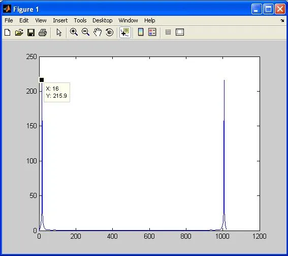
Figure 1. Output signal (d_out) from Verilog code plotted in MATLAB
Therefore, comparing the output waveforms obtained from the MATLAB code and the Verilog code, we can conclude that the two outputs are almost the same.
In summary, the Low Pass FIR filter was implemented in MATLAB using its built-in functions and the FDA tool, and also implemented using Verilog.
Explore Verilog Logic Gates, Mux & Encoders
- Verilog HDL Code for All Logic Gates
- 2-to-4 Decoder (Verilog HDL Code)
- 4-to-1 Multiplexer and 1-to-4 Demultiplexer (Verilog Code)
- Verilog Code: 1-to-4 Demultiplexer
- 8-to-1 Multiplexer (Verilog HDL Code)
- 8-to-3 Encoder Without Priority (Verilog)
- 8-to-3 Priority Encoder (Verilog)
- 8-to-3 Priority Encoder (Verilog Code)
- 1-Bit and 4-Bit Comparator Design (Verilog)
Explore Verilog Flip-Flops, Counters & Registers
- T, D, SR, JK Flip Flop (Verilog HDL Code)
- D Flip Flop Synchronous Reset (Verilog)
- D Flip Flop Without Reset (Verilog)
- Verilog Code for Binary Up-Down Counter
- Verilog HDL: BCD & Gray Counters
- 4-bit Down Counter (Verilog Code Test Bench)
- 4-bit Binary Asynchronous Reset Counter (Verilog)
- 4-bit Binary Synchronous Reset Counter (Verilog)
- 4-bit BCD Asynchronous Reset Counter (Verilog)
- 4-bit BCD Synchronous Reset Counter (Verilog Code)
- 4-bit Mod-13 Counter (Verilog Code Test Bench)
- Shift Left / Shift Right Register (Verilog)
- Parallel Load Shift Left Register (Verilog Code)
- PRBS Generator (Verilog Code Test Bench)
Explore Verilog Math, Processing & Memory
- Full Adder (Verilog HDL Code)
- Verilog Code: Half Adder, Half Subtractor, Full Subtractor
- 32-Bit ALU (Verilog Code)
- RAM / ROM (Verilog Code)
- Asynchronous FIFO (Verilog Code Test Bench)
- Asynchronous FIFO Design (Verilog Code and Explanation)
- Mealy / Moore Machine (Verilog)
- Low Pass FIR Filter (Verilog Code)
- 4-bit Binary to Gray Counter Converter in Verilog