
Optical vs. Microwave Spectrum Analyzers: Key Differences
Advertisement
This article compares optical spectrum analyzers and microwave spectrum analyzers, highlighting the key distinctions between these two essential test and measurement tools used for analyzing signals in different domains.
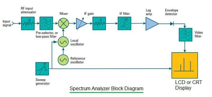
Figure 1: Microwave Spectrum Analyzer Block Diagram
Microwave Spectrum Analyzer
A microwave spectrum analyzer is used to measure radio frequency signals in the microwave and other frequency bands. This type of analyzer plots the microwave signal in X-Y coordinates.
- X-axis: Represents frequency (in Hz, MHz, or GHz).
- Y-axis: Represents power (in dB).
Essentially, it’s a frequency domain analysis tool.
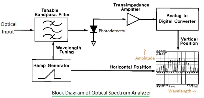
Figure 2: Optical Spectrum Analyzer Block Diagram
Optical Spectrum Analyzer
An optical spectrum analyzer is used to measure optical signals within optical bands. Like its microwave counterpart, it plots the optical signal in X-Y coordinates.
- X-axis: Represents wavelength (in µm or nm).
- Y-axis: Represents amplitude or power (in dB).
While both analyzers present data in a similar format, their internal architectures and the types of signals they analyze are quite different.
Key Differences: A Comparative Table
The following table summarizes the major differences between optical and microwave spectrum analyzers:
| Parameter | Microwave Spectrum Analyzer | Optical Spectrum Analyzer |
|---|---|---|
| Measurement | Microwave signal | Optical signal |
| Plot Dimensions | • X-axis: Frequency • Y-axis: Power (dB) | • X-axis: Wavelength • Y-axis: Power (dB) |
| Average Noise Level | • Non-zero average noise level • Determined by Resolution Bandwidth (RBW) • Noise width determined by Video Bandwidth (VBW) | • Zero average noise level • Doesn’t depend on RBW • Root Mean Square (RMS) noise level determined by VBW |
| Sensitivity | Defined as the average noise level. | Equivalent to six times the RMS value of noise. |
| Detector Type | Simple diode-based envelope detector. | Photodiode-based detector. |
RBW represents Resolution Bandwidth, and VBW represents Video Bandwidth.
Continue Learning Fiber Optic Fundamentals & Tutorials
- Understanding Optical Fiber Communication
- Understanding Plastic Optical Fiber
- Fiber Optic Sensors: Types, Working Principles & Applications
- RF Over Fiber: Advantages, Disadvantages & Key Differences
- THz to Optical Conversion in 6G Wireless
- Quantum Key Distribution Over Fiber
- Optical Circuit Switching vs Burst Switching vs Packet Switching
Technology Comparisons (Fiber vs. Others)
- Fiber vs Microwave
- Copper vs Fiber Optic Cable Comparison
- Glass Optical Fiber vs Plastic Optical Fiber (GOF vs POF)
- Active vs Passive Optical Networks (AON vs PON)
- 5G vs Fiber Optic
Explore More Optical Networking Components
- Optical Switching Basics
- Optical Transceiver Explained
- Optical Add-Drop Multiplexer (OADM) Explained
- What is a ROADM (Reconfigurable Optical Add-Drop Mux)?
- Optical Fiber Connectors (FC, SC, ST, LC, DIN)
- Optical Amplifiers & Repeaters
- Optical Wavelength Converters
- Optical Filter Basics
- Optical Equalizer Basics
- Optical Transimpedance Amplifier
- Optical Sensors: Advantages & Disadvantages
- Optical Biosensors: Working, Types & Applications