
VCO vs PLL: Difference Between Voltage Controlled Oscillator and PLL
Advertisement
Voltage Controlled Oscillators (VCOs) and Phase Locked Loops (PLLs) are essential building blocks in RF, microwave, and digital communication systems. A VCO generates an output frequency that varies with the applied control voltage, whereas a PLL combines a VCO with a feedback control loop to generate highly stable and accurate frequencies. Understanding the difference between VCO and PLL is important for designing frequency synthesizers, wireless transceivers, radar systems, satellite communication equipment, and clock generation circuits.
Whether you are tuning a radio to a specific station, transmitting a 5G signal, or tracking a GPS satellite, your hardware needs a reliable “heartbeat” at a very specific frequency. To generate and control these frequencies, engineers rely on two fundamental concepts that work hand in hand: the VCO (Voltage Controlled Oscillator) and the PLL (Phase Locked Loop).
What is VCO (Voltage-Controlled Oscillator) ?
A Voltage Controlled Oscillator is exactly what it sounds like an electronic circuit that generates a repeating signal (an oscillation or frequency), where the output frequency is directly controlled by an input DC voltage.
If you increase the input voltage, the output frequency goes up. If you decrease the voltage, the frequency goes down.
How VCO Works
Internally, most RF VCOs rely on an LC Tank circuit (an inductor and a capacitor) to create resonance. The secret ingredient is a Varactor Diode. A varactor acts as a variable capacitor; when you change the voltage applied to it, its capacitance changes. Because capacitance dictates the resonant frequency of the LC circuit, changing the input voltage smoothly changes the output RF frequency.
Benefits of VCO
- A single VCO can be swept across a massive range of frequencies simply by altering the voltage.
- Because it reacts instantly to voltage changes, it can hop between frequencies very quickly.
- It offers a smooth, analog spectrum of frequencies rather than rigid steps.
- The circuitry is relatively simple, making it easy to integrate into small devices without draining the battery.
Drawbacks of VCO
- The output frequency will slowly drift over time, turning away from the target channel.
- Slight changes in ambient temperature or tiny fluctuations in the device’s power supply will cause the frequency to jump.
- The signal isn’t perfectly clean; it has microscopic jitters that degrade signal clarity.
To solve these drawbacks, engineers rarely use a VCO completely by itself in modern communications. Instead, they put it inside a PLL.
What is PLL (Phase Locked Loop) ?
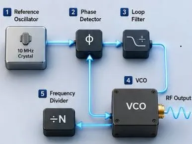
A Phase Locked Loop is a closed loop feedback control system. Its entire purpose is to take the output of a VCO and lock it to a highly stable, hyper accurate reference frequency. When a PLL achieves its goal, the system is said to be “Locked.”
How PLL works
A PLL is not a replacement for a VCO; rather, a PLL uses a VCO as its core component.
- The Reference Oscillator: The system starts with a highly stable frequency, usually generated by a precise Quartz Crystal (e.g. exactly 10 MHz). Quartz doesn’t drift with temperature the way a VCO does.
- The Phase Detector: This acts as a comparator. It looks at two signals: the perfectly stable Reference frequency and a feedback signal coming from the VCO. It compares their phases.
- The Loop Filter: If the Phase Detector notices the VCO is drifting away from the reference, it generates an error signal. The Loop Filter smooths this error signal out into a clean DC Control Voltage.
- The VCO: This clean DC voltage is fed directly into the VCO. If the VCO was drifting too high, the voltage tells it to slow down. If it was drifting too low, the voltage tells it to speed up.
- The Frequency Divider: Because the VCO might be outputting a signal in the Gigahertz range and the crystal is only in the Megahertz range, a divider steps the VCO’s frequency down so it can be accurately compared to the reference at the Phase Detector as per specification.
Through this continuous loop, the PLL constantly changes VCO’s control voltage, ensuring its massive output frequency remains perfectly synchronized with the ultra stable crystal.
Difference between VCO and PLL
| Feature | VCO (Voltage Controlled Oscillator) | PLL (Phase Locked Loop) |
|---|---|---|
| Definition | A circuit that generates a frequency based on an input voltage. | A control system that synchronizes a generated frequency to a stable reference. |
| System Role | The physical generator of the RF signal. | The controller that manages the generator. |
| Component Hierarchy | Operates as a standalone component. | A larger system that contains a VCO inside it. |
| Frequency Stability | Poor. Highly susceptible to drifting over time. | Excellent. Highly stable, immune to drift once “locked.” |
| Environmental Sensitivity | High. Frequency changes with temperature and voltage shifts. | Low. Compensates for temperature and voltage variations automatically. |
| Phase Noise | Generally higher (more noise/jitter). | Significantly lower (cleaner signal). |
| Complexity | Simple circuit | Complex circuit |
| Cost | Lower | Higher |
Summary
A VCO provides variable frequency signal generation, while a PLL stabilizes and controls that frequency using feedback. Together they form the foundation of modern RF frequency synthesis and timing systems.
Continue Learning Voltage Controlled Oscillators (VCO)
Deep dives into how voltage controlled oscillators generate frequencies, how they are tuned, and how they integrate with PLLs.
- Voltage Controlled Oscillators (VCOs) Overview
- VCO Basics (Voltage Controlled Oscillators)
- VCO Tuning Constant and Tuning Methods
- Difference Between VCO and PLL
- NCO vs VCO: Understanding the Differences
- VCO vs VCXO Differences
- MAX2871 Wideband PLL/VCO IC: Pin Diagram and Applications
Explore Phase-Locked Loops (PLL) & IC Applications
Understand the core mechanics of Phase Locked Loops and explore application notes for popular PLL chips used in RF design.