
Pros & Cons of 5 Common RF Filter Technologies Compared
Advertisement
In RF and microwave engineering, deciding on the mathematical response of your filter (like Butterworth or Chebyshev) is only the first step. The next, often more critical step, is choosing the physical topology, actual materials and structure used to build the filter.
The physical topology dictates the filter’s Size, Weight, Power and Cost (SWaP-C), as well as its maximum frequency and insertion loss. From tiny IoT wearables to massive military radar systems, selecting the right physical implementation is essential to optimize the design. Let us explore five most common RF filter technologies, how they work and differences between them.
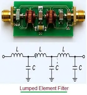
1. Lumped Element Filters
Lumped element filters are built using discrete, surface mount inductors (L) and capacitors (C) soldered onto a printed circuit board (PCB).
- They use conventional circuitry to create resonant LC networks that block or pass signals.
- They are incredibly small, exceptionally cheap to manufacture in high volumes, and easy to design.
- As frequencies push into the higher gigahertz range, parasitic capacitance and conductor losses degrade the filter’s Quality factor (Q). They become “lossy” and struggle to provide sharp filtering at high frequencies.
- IoT devices, consumer wireless products, and low frequency commercial instrumentation (typically under 4.5 GHz).
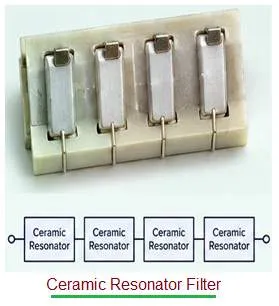
2. Ceramic Resonator Filters
Instead of discrete inductors and capacitors, these filters use blocks of high dielectric ceramic material to trap and filter electromagnetic energy.
- The high dielectric constant of the ceramic shrinks the wavelength of the RF signal, allowing the filter to be physically compact while achieving a much higher unloaded Q factor than lumped elements.
- They offer a fantastic middle ground. They provide much steeper rejection skirts and lower insertion loss than lumped elements, without the massive size of a cavity filter.
- They are slightly larger and more expensive than lumped elements, and typically max out around 6 GHz.
- Cellular base stations, GPS/GNSS receivers, aerospace, and satellite communications where high selectivity is needed in a moderate footprint.
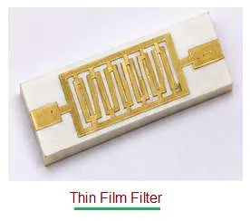
3. Thin Film Filters
Thin film filters are manufactured using semiconductor style photolithography to print incredibly precise transmission lines onto low loss dielectric substrates (like alumina or quartz).
- By treating the printed lines as distributed RF elements, these filters manipulate the signal on a microscopic scale.
- Because the manufacturing process is so precise, thin film filters offer perfect unit to unit repeatability. They are highly compact and perform exceptionally well at extreme microwave and millimeter wave (mmWave) frequencies (up to 40 GHz and beyond).
- They cannot handle massive amounts of raw RF power, and their Q-factor, while good, doesn’t match the extreme performance of cavity filters.
- 5G/6G mmWave applications, phased array radars, and high frequency test and measurement systems.
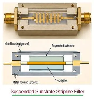
4. Suspended Substrate Stripline (SSS) Filters
SSS technology bridges the gap between printed circuit boards and machined metal filters.
- A thin dielectric circuit board is suspended inside a precision machined, air filled metal enclosure. Because the electromagnetic field travels mostly through the air rather than the PCB material, dielectric loss is virtually eliminated.
- SSS filters are famous for delivering ultra wide bandwidths, excellent power handling and very low insertion loss.
- They require a larger, heavier mechanical structure to house the suspended substrate, making them bulkier and more expensive to manufacture than standard PCB filters.
- Electronic Warfare (EW), broadband radar, and wideband laboratory instrumentation.
5. Cavity Filters
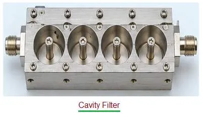
Cavity filters are large, precision machined metal boxes containing hollow chambers (cavities) and metallic tuning posts.
- The physical dimensions of the hollow cavities dictate exactly which frequencies resonate and pass through, and which are stopped.
- Cavity filters offer the ultimate, undisputed highest performance. They provide the highest Q factor, the absolute lowest insertion loss, the sharpest “brick wall” rejection, and can handle hundreds (or thousands) of watts of raw RF power without melting.
- They are the largest, heaviest, and most expensive filters on this list.
- Mission critical military radar, deep space satellite payloads, and high power broadcasting where every single decibel of loss or interference is unacceptable.
Comparison Matrix: Which Topology is Right for Your Design?
| Filter Technology | Primary Strength | Main Trade-off | Power Handling | Max Frequency (Approx.) | Ideal Use Case |
|---|---|---|---|---|---|
| Lumped Element | Smallest size, lowest cost. | Poor Q factor at higher frequencies. | Low | ~4.5 GHz | IoT, consumer wireless, low cost devices. |
| Ceramic Resonator | High Q and excellent selectivity in a small package. | Moderate weight and limited frequency ceiling. | Low to Medium | ~6 GHz | Cellular infrastructure, GPS, satellite. |
| Thin Film | Extreme precision, repeatability, and small size. | Moderate power handling capability. | Low to Medium | ~40 GHz+ | mmWave 5G, phased arrays, precise test gear. |
| Suspended Substrate (SSS) | Ultra Wide bandwidth and low insertion loss. | Requires a bulky mechanical housing. | High | ~50 GHz | Broadband EW, wideband radar, comms. |
| Cavity | Ultimate performance, highest Q, zero loss. | Largest, heaviest, and most expensive. | Very High | ~67 GHz+ | High power military radar, aerospace, base stations. |
Summary
Selecting the right filter depends on Frequency, Bandwidth, Power and Budget. If you are designing a cheap Bluetooth wearable, the Lumped Element is your only realistic choice. If you are designing a high frequency mmWave array, look to Thin Film. If you need to filter a multi kilowatt radar pulse, nothing but a Cavity filter is the ideal choice. Finally, for those tricky wideband defense applications, Suspended Substrate (SSS) offers the perfect blend of power and bandwidth.
Continue Learning Filter Fundamentals & Terminology
- Lumped Element Filter : Key Advantages & Disadvantages
- Microstrip Based RF Low Pass Filter Design Example
- Understanding Filter Terms
- RF Filters : Types, Selection Guide, Advantages & Disadvantages
- Active vs Passive Filters
- Analog vs Digital Filters
- Butterworth, Chebyshev, Bessel, and Elliptic Filters
- FIR Filter vs IIR Filter
- Understanding CIC (Cascaded Integrator-Comb) Filters
- Pi Filter: Advantages & Disadvantages
- Active vs Passive Harmonic Filters