
Smith Chart Fundamentals
Advertisement
This document covers the fundamentals of the Smith chart and the rules for impedance matching using it. It outlines the equations that the Smith chart is derived from.
The following two equations are essential for constructing the Smith chart. They define how to draw constant resistance circles and constant reactance circles.
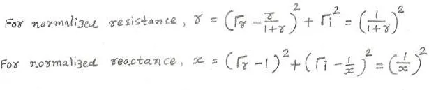
Superimposing circles derived from the equations above onto the complex polar form of the normalized impedance Z-plane on the unit circle creates the Smith chart.
- Normalized resistance circle (r range):
- Normalized reactance circle (x range):
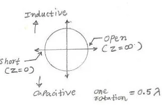
As illustrated in the figure, the upper portion of the Smith chart represents inductive components, while the lower portion represents capacitive components. Furthermore, the left side origin corresponds to an impedance (Z) of zero (short circuit), and the right side origin corresponds to an impedance of infinite value (open circuit). A complete rotation on the Smith chart represents half a wavelength ().
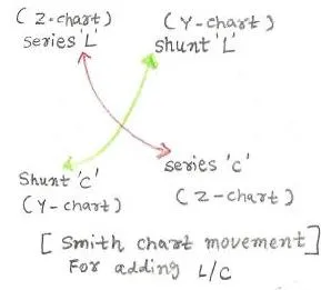
The figure above assists in mapping inductive (L) and capacitive (C) components on the Smith chart for impedance matching and other calculations.
- Adding a series L component on the Z-chart (Impedance chart) requires moving clockwise by the corresponding value.
- Adding a series C component on the Y-chart (Admittance chart) requires moving counter-clockwise.
It’s important to remember that rotating the reflection coefficient chart in the Z-Smith chart by 180 degrees results in the Y-Smith chart.
- Adding a shunt L on the Y-chart requires moving counter-clockwise.
- Adding a shunt C on the Y-chart requires moving clockwise.
Continue Learning Microwave Fundamentals & Communication Systems
- Microwave Frequency: Advantages & Disadvantages
- Microwave Communication: Advantages & Disadvantages
- Microwave Backhaul Overview
- Microwave Transmission KPIs (Key Performance Indicators)
- Microwave Transmission Line Basics
- Microwave Coaxial Line Basics
- Microwave Semiconductor Devices
- Microwave Semiconductor Materials Comparison
Explore Non-Telecom Applications: Medical, Heating & Defense
- Microwave Heating Principles & Applications
- Microwave vs Solid State RF Energy Heating Ovens
- Microwave Diathermy: Advantages & Disadvantages
- Microwave Ablation
- High Power Microwave Weapons
- Laser vs Microwave Weapons
- Laser vs Microwave in Trapped Ion Quantum Computing
- Microwave Landing System Basics
- Microwave Sensor vs PIR Sensor