
What is L298N Motor Driver IC? Pin Diagram and Applications
Advertisement
The L298N is a dual full H-bridge motor driver capable of controlling two DC motors or one bipolar stepper motor independently. It is widely used in robotics, automation, Arduino projects, and industrial motor control systems.
Key features of L298N
This breakout board utilizes the ST L298N IC to independently and bidirectionally control high-current loads like DC motors and stepper motors.
- High Power Capacity: Drives up to 2 Amps per channel, with operating voltages from 5V to 35V.
- Dual H-Bridge: Can independently control the speed and direction of two DC motors, or precisely step one 4-wire bipolar stepper motor.
- On-board 5V Regulator: Can supply 5V logic power back to an attached microcontroller (Note: the 5V enable jumper must be removed if supplying > 12V to the motor power input).
- Protection: Equipped with built-in protection diodes to suppress back EMF from inductive motor loads.
L298N Pin Diagram
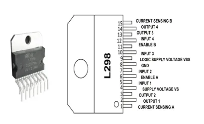
L298N (Dual H-Bridge Motor Driver Module)
| Pin / Terminal Name | Description |
|---|---|
| +12V Power | Power supply input for motors (DC 5V - 35V). |
| Power GND | Common ground connection. |
| +5V Power | +5V logic output supply (if 5V Enable jumper is ON) or +5V logic input. |
| 5V Enable | Jumper to enable the on-board +5V regulated power supply. |
| Output A | Output terminals (OUT1, OUT2) to connect Motor A. |
| Output B | Output terminals (OUT3, OUT4) to connect Motor B. |
| A Enable (ENA) | Enable signal input for Motor A (can be used for PWM speed control). |
| B Enable (ENB) | Enable signal input for Motor B (can be used for PWM speed control). |
| Logic Input (IN1, IN2) | Control signal inputs for Motor A direction. |
| Logic Input (IN3, IN4) | Control signal inputs for Motor B direction. |
Example Use Case
Arduino Rover Chassis: You are building a 2-wheel drive autonomous rover. A 9V battery connects to the module’s power block, and the module’s onboard 5V regulator powers the Arduino. The left motor connects to OUT1/OUT2, and the right motor to OUT3/OUT4. By sending logic signals from the Arduino to IN1-IN4, the rover can drive forward, reverse, or spin in place by turning the wheels in opposite directions. Applying a PWM signal to ENA and ENB allows the Arduino to modulate the rover’s speed.
Applications of L298N
Wheeled robots, CNC machinery, automated blinds/curtains, and camera sliders.
Summary
L298N enables bidirectional speed and direction control of DC and stepper motors.