
HMC5883 Magnetometer IC Pin Diagram, Circuit and Applications
Advertisement
The HMC5883 is a three axis digital magnetometer IC used to measure the Earth’s magnetic field for electronic compass and navigation applications. It communicates through an I�C interface and is widely used in drones, robotics, smartphones, wearable devices, and navigation systems. This article explains its pin diagram, working principle, circuit, features, and applications.
Key features of HMC5883
- Highly Integrated & Compact: Features 3-axis magnetoresistive (AMR) sensors and an ASIC in a tiny 3.0 x 3.0 x 0.9 mm LCC surface mount package.
- High Resolution & Accuracy: Includes a 12-bit ADC that provides 5 milli-Gauss resolution, enabling precise 1 to 2 degrees compass heading accuracy.
- Wide Magnetic Field Range: Capable of measuring magnetic fields from milli-gauss up to +/- 8 Gauss (Oe).
- Low Power/Voltage Operation: Operates on low voltage (1.6V to 3.3V) with multiple power management modes (Continuous, Single-Measurement, Idle, Sleep, and Off), making it ideal for battery-powered devices.
- Communication Interface: Standard I2C digital interface supporting up to 400 kHz fast mode for easy connection to microcontrollers.
- Built-in Support Circuits: Features automatic degaussing strap drivers (Set/Reset) and offset cancellation, plus a Built-In Self Test for low-cost production functionality testing.
- Algorithm Support: Compatible with software libraries for compassing heading, hard iron/soft iron calibration, and auto-calibration.
HMC5883 Pin Diagram
Here’s a look at the HMC5883 pin diagram:
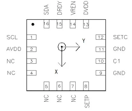
| Pin No. | Pin Name | Type | Function |
|---|---|---|---|
| 1 | SCL | Digital Input | I²C serial clock input used for communication with the host microcontroller. |
| 2 | AVDD | Power | Analog power supply input (typically 2.16 V to 3.6 V). Supplies the analog sensing circuitry. |
| 3 | NC | — | No internal connection. Leave unconnected. |
| 4 | NC | — | No internal connection. |
| 5 | NC | — | No internal connection. |
| 6 | NC | — | No internal connection. |
| 7 | NC | — | No internal connection. |
| 8 | SETP | Analog | Positive terminal for the internal set/reset strap capacitor (C2). Used for magnetic offset calibration and sensor reset. |
| 9 | GND | Ground | Ground connection for the analog circuitry. |
| 10 | C1 | Analog | Reservoir capacitor connection. An external capacitor is connected to this pin for internal charge storage. |
| 11 | GND | Ground | Ground connection for the digital/analog circuitry. Connect to PCB ground. |
| 12 | SETC | Analog | Negative terminal (driver side) of the set/reset strap capacitor (C2). Used together with SETP. |
| 13 | DVDD | Power | Digital power supply input for the I²C interface and digital logic. |
| 14 | VREN | Digital Input | Voltage regulator enable. Connect to AVDD for single-supply operation or GND for dual-supply operation. |
| 15 | DRDY | Digital Output | Data Ready output. Indicates that new magnetic field measurement data is available in the output registers. |
| 16 | SDA | Bidirectional | I²C serial data line used for configuration and reading X, Y, and Z magnetic field data. |
Example Use Case Smartphone Digital Compass & Pedestrian Navigation
The HMC5883 is integrated into a smartphone to provide map orientation and digital compass capabilities for pedestrian navigation.
The HMC5883 is connected to the smartphone’s host processor via the two-wire I2C interface. It is powered by the phone’s battery system using a nominal 1.8V digital supply and 2.5V analog supply. Two external capacitors (a 4.7 µF reservoir capacitor and a 0.22 µF set/reset capacitor) are added to the circuit to handle the brief, high-current pulses needed for the built-in sensor degaussing (Set/Reset) strap.
Applications of HMC5883
- Mobile Phones and Smartphones
- Netbooks and Laptops
- Consumer Electronics
- Auto Navigation Systems
- Personal Navigation Devices (PNDs)
- Low cost compassing and magnetometry
Summary
The HMC5883 provides accurate digital magnetic field measurements for orientation and navigation. Its low power consumption makes it suitable for portable embedded systems.