
Squelch Circuits: Suppressing Noise in Radio Receivers
Advertisement
The term “squelch” refers to the act of suppressing or completely crushing something. In the context of radio receivers, squelch is a circuit that mutes the audio output in the absence of a desired RF signal.
The main idea behind squelch is to avoid the annoying noise that a receiver produces when no signal is present. Imagine a mobile phone constantly outputting static in the absence of a call. Nobody wants that! Squelch circuits solve this problem by activating the receiver’s audio output only when a valid signal is detected.
Function of Squelch Circuit
Let’s delve into how a squelch circuit works.
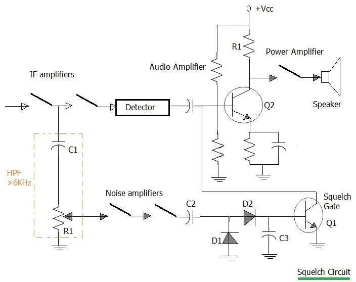 Image alt: squelch circuit
As shown in the figure above, a squelch circuit typically consists of a high-pass filter and an audio amplifier, along with transistors Q1 and Q2. Q1 acts as a squelch gate controlling the base of transistor Q2.
When Audio is Present
Most audio frequencies fall below 4 kHz. The high-pass filter is designed to block these lower frequencies. Therefore, when a legitimate audio signal is present:
- No squelch voltage develops at the receiver output.
- Transistor Q1 is cut off, allowing transistor Q2 to be biased normally.
- The audio signal passes through the audio power amplifier to the speaker, and you hear the sound.
When Noise is Present
Noise signals generally contain higher frequencies. Here’s how the squelch circuit responds to noise:
- The high-frequency noise is amplified by the two transistor stages.
- This amplified noise is then converted into a DC control voltage using a rectifier-voltage doubler circuit (comprising D1, D2, C2, and C3).
- The DC voltage drives transistor Q1 into saturation.
- The base current of transistor Q2 is shunted away from Q1.
- As a result, no audio amplification occurs, and the receiver remains silent.
In essence, the squelch circuit acts as a gatekeeper, allowing audio signals to pass while blocking unwanted noise. This type of circuit is common in various communication receivers. You might also hear it referred to as a “mute circuit.”
Continue Learning Digital Mobile Radio (DMR) & Professional Mobile Radio
- DMR Radio Basics Tutorial
- DMR Tier 1 vs Tier 2 vs Tier 3: Understanding the Differences
- DMR vs dPMR Comparison
- NXDN vs DMR Comparison
- Digital Mobile Radio (DMR) Interview Questions and Answers
Explore More Radio Technologies & Standards
- TETRA Radio System Tutorial
- LITRA (LTE Integrated Trunked Radio) Explained
- OpenSky Radio System Basics
- Public Safety Radio Frequencies (USA)
- Two-Way Radio Headsets Basics
- Understanding CBRS (Citizens Broadband Radio Service)
- Commercial and Concept Radio Systems
- PMR446 Radio Frequency Channels
Explore Broadcasting, AM/FM & Ham Radio
- Regular FM Radio Broadcasting Basics
- HD Radio Technology & AM/FM Spectrum Explained
- Digital Radio Mondiale (DRM)
- IBOC Basics (In-Band On-Channel Digital Radio)
- Radio Broadcasting: Advantages & Disadvantages
- Analog vs Digital Radio
- Amateur Radio Bands and Frequencies
- Ham Radio: Advantages & Disadvantages
- Internet Radio: Advantages & Disadvantages