
LTE PRACH Channel: Physical Random Access Channel Explained
Advertisement
This page describes the LTE Physical Random Access Channel (PRACH). It also provides links to WCDMA PRACH and GSM RACH channel basics. This channel is used to carry random access preambles, which are used for initiating the random access procedure.
The basic structure is shown in the figure below. A random access preamble includes a CP (Cyclic Prefix), a sequence, and a guard time. This carries the random access preamble. The RACH transport channel is mapped to this.
- Carries the random access preamble that a UE sends to access the network.
- Consists of 72 sub-carriers in the frequency domain.
- There are 4 different RA (random access) preamble formats defined in LTE FDD specifications.
The same have been mentioned in Table 1 below. It consists of different preamble and CP durations to accommodate different cell sizes.
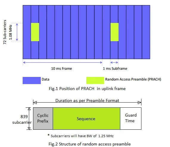
Table 1: LTE PRACH Preamble Formats
| Preamble Format | CP Length (ms) | Sequence Length (ms) | Guard Time (ms) | Total Length (ms) | Guard time equiv. dist. (Km) | Typical Max. cell range (Km) |
|---|---|---|---|---|---|---|
| 0 | 0.10 | 0.8 | 0.10 | 1 | 30 | 15 |
| 1 | 0.68 | 0.8 | 0.52 | 2 | 156 | 78 |
| 2 | 0.2 | 1.6 | 0.2 | 2 | 60 | 30 |
| 3 | 0.68 | 1.6 | 0.72 | 3 | 216 | 108 |
The preamble format to be used in a specific cell is signaled to the UE using the PRACH configuration index. This information is broadcast in SIB-2 (System Information Block Type 2). The PRACH configuration index also indicates the SFN (System Frame Number) and subframes, providing the exact position of the random access preamble.
Table 2: LTE PRACH Channel Configuration Index
| PRACH Configuration Index | Preamble Format | SFN | Subframe number |
|---|---|---|---|
| 0 | 0 | Even | 1 |
| 1 | 0 | Even | 4 |
| 2 | 0 | Even | 7 |
| 3 | 0 | Any | 1 |
| 4 | 0 | Any | 4 |
| 5 | 0 | Any | 7 |
| 6 | 0 | Any | 1, 6 |
| 7 | 0 | Any | 2, 7 |
| 8 | 0 | Any | 3, 8 |
| 9 | 0 | Any | 1, 4, 7 |
| 10 | 0 | Any | 2, 5, 8 |
| 11 | 0 | Any | 3, 6, 9 |
| 12 | 0 | Any | 0, 2, 4, 6, 8 |
| 13 | 0 | Any | 1, 3, 5, 7, 9 |
| 14 | 0 | Any | 0 to 9 |
| 15 | 0 | Even | 9 |
| 16 | 1 | Even | 1 |
| 17 | 1 | Even | 4 |
| 18 | 1 | Even | 7 |
| 19 | 1 | Any | 1 |
| 20 | 1 | Any | 4 |
| 21 | 1 | Any | 7 |
| 22 | 1 | Any | 1, 6 |
| 23 | 1 | Any | 2, 7 |
| 24 | 1 | Any | 3, 8 |
| 25 | 1 | Any | 1, 4, 7 |
| 26 | 1 | Any | 2, 5, 8 |
| 27 | 1 | Any | 3, 6, 9 |
| 28 | 1 | Any | 0, 2, 4, 6, 8 |
| 29 | 1 | Any | 1, 3, 5, 7, 9 |
| 30 | - | - | - |
| 31 | 1 | Even | 0 |
| 32 | 2 | Even | 1 |
| 33 | 2 | Even | 4 |
| 34 | 2 | Even | 7 |
| 35 | 2 | Any | 1 |
| 36 | 2 | Any | 4 |
| 37 | 2 | Any | 7 |
| 38 | 2 | Any | 1, 6 |
| 39 | 2 | Any | 2, 7 |
| 40 | 2 | Any | 3, 8 |
| 41 | 2 | Any | 1, 4, 7 |
| 42 | 2 | Any | 2, 5, 8 |
| 43 | 2 | Any | 3, 6, 9 |
| 44 | 2 | Any | 0, 2, 4, 6, 8 |
| 45 | 2 | Any | 1, 3, 5, 7, 9 |
| 46 | - | - | - |
| 47 | 2 | Even | 9 |
| 48 | 3 | Even | 1 |
| 49 | 3 | Even | 4 |
| 50 | 3 | Even | 7 |
| 51 | 3 | Any | 1 |
| 52 | 3 | Any | 4 |
| 53 | 3 | Any | 7 |
| 54 | 3 | Any | 1, 6 |
| 55 | 3 | Any | 2, 7 |
| 56 | 3 | Any | 3, 8 |
| 57 | 3 | Any | 1, 4, 7 |
| 58 | 3 | Any | 2, 5, 8 |
| 59 | 3 | Any | 3, 6, 9 |
| 60 | - | - | - |
| 61 | - | - | - |
| 62 | - | - | - |
| 63 | 3 | Even | 9 |
The preamble uses a subcarrier spacing of 1.25 kHz instead of the usual 15 kHz. The random access preamble occupies 1, 2, or 3 subframes in the time domain (1, 2, or 3 ms) and 839 subcarriers in the frequency domain (1.05 MHz). There’s a 15 kHz guard band on both sides, resulting in a total bandwidth of 1.08 MHz (equal to 6 RBs - Resource Blocks).
The position of the LTE random access preamble is defined by the PRACH frequency offset parameter carried in SIB-2.
There can be a maximum of 1 random access preamble in a subframe, but multiple UEs can use it. Multiple UEs using the same preamble resource allocations are differentiated by their unique preamble sequences. As mentioned in Table 2, a maximum of 64 preamble sequences are divided into Group A and Group B.
The LTE UE selects a sequence from these two groups based on the size of the uplink packet and radio conditions. This helps the eNodeB to estimate the PUSCH (Physical Uplink Shared Channel) resources needed for UE uplink transfer.
Sequences in Group A are used for smaller-sized packets or larger-sized packets under poor radio conditions. Sequences in Group B are used for larger-sized packets under good radio conditions.
- LTE PRACH channel reference: 3GPP TS 36.211
Explore More LTE Channels
- LTE PBCH Physical Broadcast Channel
- LTE PCFICH Channel : Physical Control Format Indicator Channel
- LTE PDCCH : Physical Downlink Control Channel
- LTE PDSCH Channel : Physical Downlink Shared Channel
- LTE PHICH: Physical Hybrid ARQ Indicator Channel
- LTE PMCH : Physical Multicast Channel
- LTE PUCCH: Physical Uplink Control Channel
- LTE PUSCH: Physical Uplink Shared Channel
- LTE PSS vs SSS: Primary and Secondary Synchronization Signals
- LTE Reference Signals: RS, DMRS, and SRS
Continue Learning 4G LTE
- 4G LTE Basics Tutorial
- 4G LTE Architecture: Network Elements and Interfaces
- LTE Frame Structure
- LTE Channel Types: Logical, Transport and Physical Channels
- LTE Protocol Stack: User Plane vs. Control Plane
- 4G LTE Physical Layer & its modules
- LTE Frequency Bands: FDD, TDD and E-UTRA Bands
- LTE Carrier Aggregation & its benefits
- 4G LTE Network Security
- LTE Cell Search Procedure
- LTE UE Uplink Network Entry : Random Access Procedure
- LTE Paging Procedure Mechanism and Call Flow