
IQ Imbalance: Causes, Effects, and Compensation
Advertisement
This page delves into the world of IQ imbalance, covering aspects like gain/amplitude, phase, and DC offset. It also explores the effect of these imbalances on constellation diagrams and outlines various methods used for IQ imbalance compensation/correction.
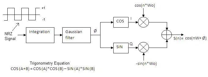
Fig.1 IQ modulator
There are three primary types of IQ imbalance:
- IQ amplitude imbalance
- IQ phase imbalance
- IQ DC offset
These imbalances are mainly introduced by the in-phase (I) and quadrature (Q) components present in Cartesian transmitters, such as those used in GMSK modulators as shown in the figure above. IQ imbalance tends to be less pronounced in homodyne architectures compared to heterodyne architectures.
Effect of IQ Imbalance on Constellation
IQ gain and phase imbalance are particularly noticeable in non-constant envelope or linear modulation schemes like QPSK and 16-QAM. These schemes rely on both amplitude and phase variations of the carrier waveform to carry information. Let’s examine the effect of IQ imbalance on a 16-QAM signal.
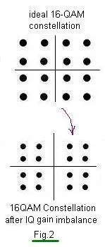
IQ gain imbalance
The I and Q components travel different paths in both the transmitter and receiver to achieve IQ-modulation and IQ-demodulation. The IQ mixer itself can introduce IQ imbalance due to its different branches. Furthermore, all other circuits through which the I and Q signals pass can also introduce gain and phase errors between these signals.
The effect of IQ gain imbalance on a 16 QAM signal is depicted in the figure above.
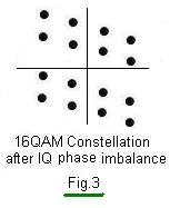
IQ phase imbalance
The effect of IQ phase imbalance on 16 QAM constellations is depicted in the figure above.
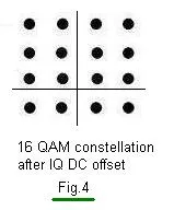
IQ DC offset
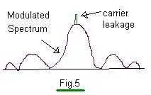
IQ DC offset arises due to differences in the DC bias applied to the I and Q signals. This IQ DC offset results in carrier leakage at the output of the modulator.
carrier leakage
Fig.4
Fig.5 depicts carrier leakage on modulated spectrum,
If the carrier leakage level is comparable to the modulated signal level, it will cause interference.
IQ Imbalance Compensation/Correction
Various methods exist to compensate for these imbalances at both the transmitter and receiver. The most common approaches involve using known patterns or modulation types. Additionally, IQ DC offset is often compensated/corrected by adjusting the DC bias applied to the I and Q signals, leading to better carrier rejection at the output.
By applying IQ compensation, we can improve the error vector magnitude of the modulated signal, which helps in decoding the signal correctly and ultimately increases the Bit Error Rate (BER) of the system.
Continue Learning Distortion & Nonlinearities (AM-AM, AM-PM)
- Understanding Distortion in RF Amplifiers
- AM-AM Conversion in Power Amplifiers
- Passive Intermodulation Distortion (PIM): Causes & Mitigation
Explore Impairments, Noise & Channel Models in MATLAB/Python
- AWGN in MATLAB
- Channel Model in MATLAB
- AWGN in Python: Adding Noise Based on SNR (dB)
- Rayleigh Fading Channel Simulation in Python
- Rician Fading Channel Simulation in Python
- Simulating DC Offset Impairment in MATLAB
- Carrier Frequency Offset Impairment in MATLAB
- MATLAB Sampling Frequency Offset Impairment
- OFDM Frequency Offset Estimation in MATLAB
- IQ Imbalance Impairment in MATLAB
- MATLAB Phase Noise Impairment
- Power Amplifier Nonlinearity Impairment in MATLAB