
Asynchronous FIFO Verilog Code and Test Bench
Advertisement
This article provides Verilog code for an Asynchronous FIFO (First-In, First-Out) and its corresponding test bench. We’ll also examine the simulated output.
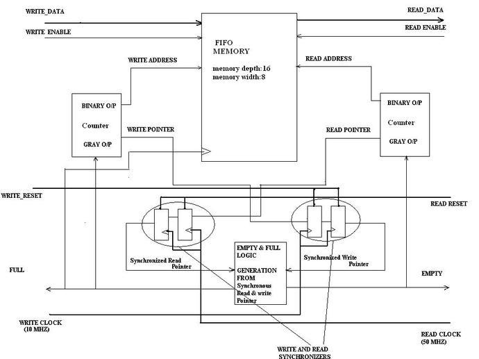
Figure 1: Asynchronous FIFO Design
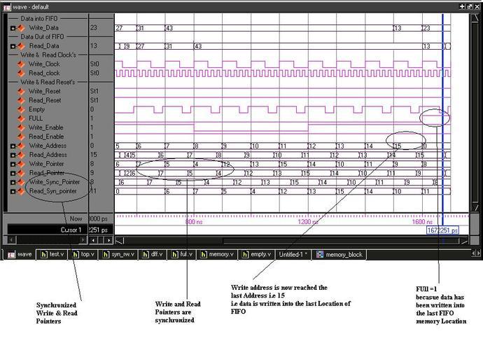
Figure 2: Simulation Output of Asynchronous FIFO
The image above (Figure 2) shows the simulation output of the Asynchronous FIFO design depicted in Figure 1.
Asynchronous FIFO Verilog Code
Here’s the Verilog code for the Asynchronous FIFO:
module tb_top();
  reg wr_clk,rd_clk;
  reg[7:0] data_in;
  wire[7:0] data_out;
  wire rd_empty,wr_full;
  reg reset_w;
  reg reset_r;
  reg write_enable,read_enable;

  top top_1(
    .wr_data(data_in),
    .rd_data(data_out),
    .wr_clk(wr_clk),
    .rd_clk(rd_clk),
    .w_reset(reset_w),
    .r_reset(reset_r),
    .write_enable(write_enable),
    .read_enable(read_enable),
    .empty(rd_empty),
    .full(wr_full)
  );

  initial begin
    #0 data_in=8'h0;
    #50_000 data_in=8'b00000001;  // DATA WHICH IS SUPPLIED
    #80_000 data_in=8'h2;
    #70_000 data_in=8'h3;
    #79_000 data_in=8'h4;
    #80_000 data_in=8'h5;
    #40_000 data_in=8'h6;
    #60_000 data_in=8'h7;
    #50_000 data_in=8'h8;
    #50_000 data_in=8'h9;
    #20_000 data_in=8'h10;
    #70_000 data_in=8'h11;
    #80_000 data_in=8'h12;
    #19_000 data_in=8'h13;
    #10_000 data_in=8'h14;
    #80_000 data_in=8'h15;
  end

  initial begin
    wr_clk=1'b0;
    write_enable=1'b0;
    read_enable=1'b0;
  end

  initial always #50000 wr_clk=~wr_clk; //end

  // READ AND WRITE CLOCK GENERATION
  rd_clk=1'b0;
  initial begin
    always #10000 rd_clk=~rd_clk;
  end

  initial reset_r=1'b0;
  begin
    initial #5000 reset_r=1'b1; //end

    initial reset_w =1'b0;
    initial #5000 reset_w=1'b1;

    initial #5000 write_enable=1'b1;

    initial #50000 read_enable=1'b1;

    initial begin
      #1000000000 $finish;
    end

    initial $monitor( "$time data_out,empty ,full= %d %d %d",data_out,rd_empty,wr_full);
  end
endmodule
Asynchronous FIFO Test Bench
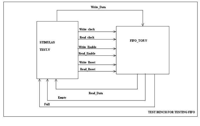
Figure 3: Asynchronous FIFO Test Bench
The image above (Figure 3) illustrates the Asynchronous FIFO Test bench setup.
Following is the pdf which describes all the modules used in this Asynchronous FIFO.
Advertisement


