 RF
RFStandard Diode in Voltage Multiplier: Working & Benefits
Advertisement
Introduction : Voltage multipliers are circuits that increase DC voltage without transformers, using diodes and capacitors in ladder arrangements. Standard diodes in these circuits allow charging and combining capacitor voltages to achieve higher output.
Diode Based Voltage Multiplier Circuit Working
This circuit generates output to about two times greater than the input voltage. Let us understand its working.
- C1 capacitor charges to Vpeak during negative half cycle.
- C2 charges to 2*Vpeak during positive half cycle.
- Output voltage touches 2*Vpeak under no load condition.
- Load current causes voltage reduction (i.e. regulation)
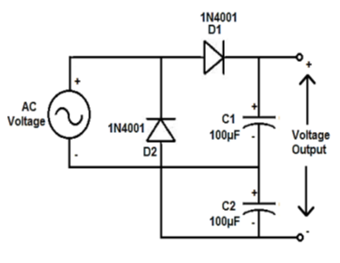
The figure-1 depicts basic doubler circuit using two diodes (D1 & D2) and capacitors (C1 & C2). It produces unregulated DC voltage twice of AC peak input. In this circuit, AC input is rectified and capacitors charge alternatively on each half cycle. It is used to generate 24V DC from 12V AC.
Advantages of Voltage Multiplier using diode
Following are some of the benefits of diode based voltage multiplier.
- It generates much higher voltage output using relatively small AC/oscillating input.
- The circuit uses light weight and compact components in its design such as diodes and capacitors. Bulky and heavy transformers are not needed.
- Components used are cheaper and hence overall circuit is in-expensive.
- The number of stages can be scaled up if higher voltage at the output is needed due to change in future requirements.
- When the load current requirement is small, diode based voltage multipliers are efficient and effective.
Conclusion: Voltage multiplier circuits using standard diodes are an efficient way to step up voltage when transformer based solutions are impractical.
Advertisement


