
Standard Diode in Signal Demodulation: Working & Benefits
Advertisement
Introduction : Signal demodulation recovers information encoded in a modulated waveform such as amplitude-modulated (AM) radio. A standard diode is often used as a rectifier/detector in demodulation circuits to extract the envelope of the modulated signal. Here, we explore how diode demodulation works and what benefits it provides in simplicity, cost and effectiveness.
Diode signal demodulation circuit working
The figure-1 depicts AM detection circuit. As shown it takes AM modulated waveform as input and generates baseband audio as output after removing RF carrier.
- Input : V(t) = Vc(1 + mcos(Wmt))cos(Wct); Where, Vc = Carrier amplitude, m = modulation inxed, Wm = modulation frequency, Wc = Carrier Frequency
- Output : Wm
Following steps describe function of components used in the circuit.
- Diode rectifies positive half cycles
- Capacitor smooths carrier frequency
- Resistor provides discharge path
- Audio frequency is recovered at its output.
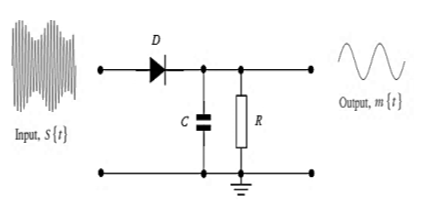
The circuit uses 1N34A diode, 100 pF capacitor and 1 MOhm resistor. Let us understand how diode based signal demodulation circuit works.
- As already mentioned, diode (D) conducts during positive half cycles of the input which charges capacitor (C) to peak voltage of the input signal.
- When input signal drops below voltage across capacitor,the diode (D) becomes reverse biased and stops conducting. As a result, capacitor discharges through resistor (R) at a rate equivalent to RC time constant.
- As explained, RC network acts as low pass filter (LPF) which follows AM signal envelope and filters out high frequency carrier waveform part.
Diode based RF detection circuit
This high frequency detection circuit requires specialized diode such as schottky diode (e.g. 1N34A) for its operation. Schottky diodes operate without DC bias for improved sensitivity.
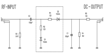
Figure-2 depicts voltage doubler in the middle; made of schottky diodes (D1 & D2) and resistors (R1 & R2). This circuit is used for RF power measurement. Let us understand its working.
- RF input is provided through C3 and terminated with R3 for impedance matching.
- During positive rf cycle input, D2 conducts and charges internal capacitance.
- During negative rf cycles, D1 conducts, which doubles peak voltage capability.
- Doubled voltage is filtered by C1 to remove RF elements.
- DC output is then fed through R4 and R5.
Advantages of signal demodulation diode
Following are some of the benefits of diode based signal demodulator.
- It is simple in design and compact in size due to requirements of fewer components.
- Such demodulators are cheaper to build.
- Passive diode detectors are robust over long period of time.
- Diodes used in the circuit such as germanium or schottky have lower forward voltage drop. Hence circuit can detect small amplitude changes more rapidly.
- As passive components are used, it does not need active power supply.
Conclusion: Using a standard diode for signal demodulation remains one of the most time tested techniques in analog electronics. For many low cost receivers and detection circuits, they remain a core component.
Tags
Advertisement


