Impedance Matching: Circuits, Methods, and Devices
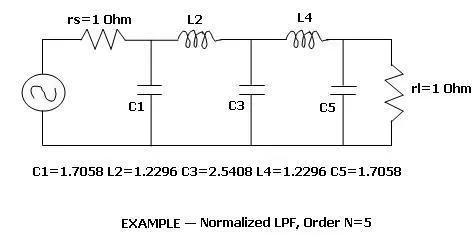
Explore impedance matching circuits (L networks, Pi networks) and devices (baluns, stubs, quarter-wave transformers) for maximum power transfer in RF systems.
Advertisement
Trace every article connected to this tag across guides, explainers, and practical RF topics. This view is especially useful when the same concept spans multiple categories.
Articles
41
Showing
1-25
Pages
1/2
Where this tag appears most
Open the categories where this topic shows up most often.
Advertisement
Tagged Articles
Showing 1-25 of 41 articles tagged with Transmission Line.
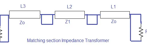
Explore impedance matching circuits (L networks, Pi networks) and devices (baluns, stubs, quarter-wave transformers) for maximum power transfer in RF systems.
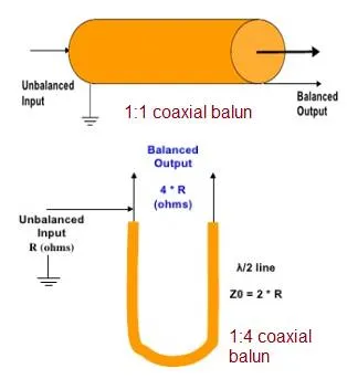
Explore types of baluns and their applications in RF and Microwave.It includes differences between LC, transformer, folded, coaxial and microstrip balun type.Explain 5 examples.
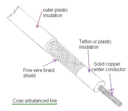
Understand the distinctions between balanced and unbalanced transmission lines, including their structure and grounding characteristics, in RF systems.
Explore the differences between coaxial cables, waveguides, and microstrip lines in RF and microwave systems, focusing on structure, principles, advantages, and applications.
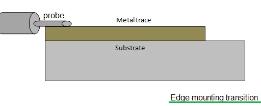
Explore coaxial to microstrip transitions: edge and vertical mounting, impedance matching, and bandwidth considerations for seamless PCB integration.
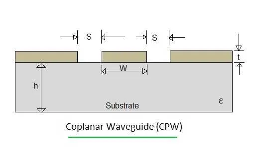
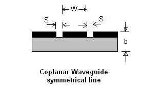
Explore coplanar waveguide (CPW) transmission lines, covering structure, functionality, advantages like ease of fabrication, and disadvantages such as surface wave losses.
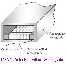
Explore the key differences between Dielectric Filled Waveguides (DFW) and Substrate Integrated Waveguides (SIW), including construction and mode of operation.
Understand the difference between electrical length and physical length in RF circuits. Learn how to calculate physical length based on electrical length and dielectric properties.
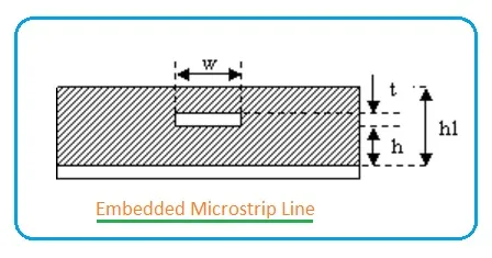
Calculate the characteristic impedance of an embedded microstrip line using this calculator and formula.
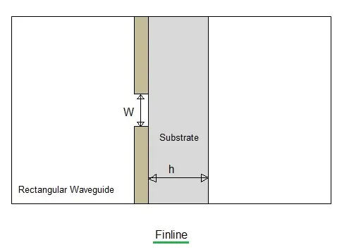
Explore the fundamentals of Finline technology, including its benefits such as low dispersion and broad bandwidth, as well as its drawbacks like complex assembly.
Explore the basics of microstrip filter structures, including stub-loaded, stepped impedance, and coupled designs.
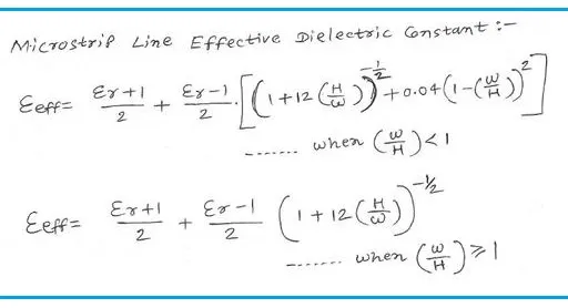
Calculate the impedance of a microstrip line using this online calculator. Explore microstrip line configurations and understand effective permittivity.
Explore the different types of microstrip lines—basic, stripline, suspended stripline, slotline, CPW, and finline—their features, advantages, and applications in RF and microwave circuits.
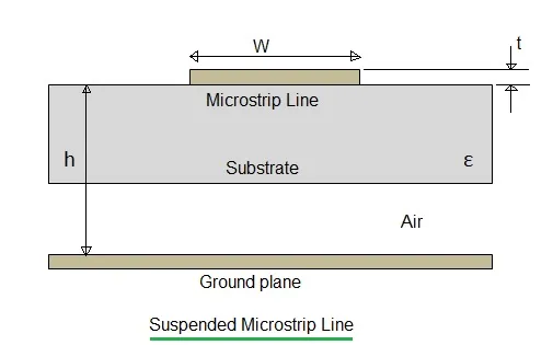
Explore the variations of microstrip lines, including inverted, suspended, and shielded designs, along with their respective advantages and disadvantages.
Explore the key differences between microstrip lines and coplanar waveguides (CPW) for RF circuit design, covering dispersion, losses, coupling, and design flexibility.
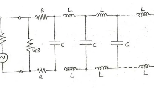
Understand the fundamentals of microwave transmission lines, including types, characteristics, and impedance calculations, essential for RF energy transport.
A comparison of planar transmission lines, including microstrip, stripline, CPW, slotline, and finline, highlighting differences in impedance, loss, and mounting.
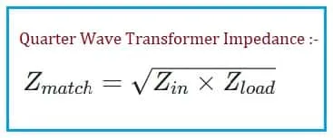
Calculate the required characteristic impedance for a quarter wave transformer to match two different transmission line impedances perfectly.
Learn about reflection and transmission coefficients, key parameters in transmission lines, their definitions, and formulas.
Understand the relationship between reflection coefficient, return loss, and VSWR in transmission lines and impedance matching. Learn how they impact signal integrity.
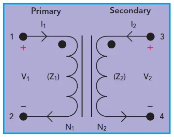
Explore RF transformer basics and types including core and wire, transmission line, LTCC, and MMIC. Learn about their working principles, construction, functions, and applications.
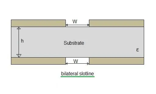
Explore slotline basics, including antipodal and bilateral slotline types. Learn about advantages, disadvantages and applications of slotlines in RF design.
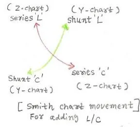
An overview of the Smith chart including its construction, components, and use in impedance matching.
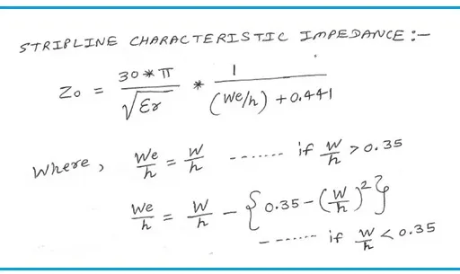
Calculate the impedance of a stripline using this online calculator. Simply input the trace width, substrate height, and relative permittivity.
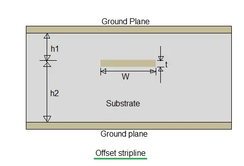
Understand types of Stripline like offset,double conductor & suspended. Explore differences between them three including advantages and disadvantages of strip lines.
Advertisement