NFC Circular Antenna Calculator
Advertisement
This page describes a calculator for an NFC antenna with a circular shape. It also mentions the formulas used to calculate the inductance of the NFC circular antenna. Links to other antenna calculators are also provided.
NFC Antenna Calculator and Example
Here’s an example of how to use the NFC Circular Antenna Calculator:
INPUTS:
- Inner radius, ri ( in mm) = 15
- Outer radius, ro ( in mm) = 22.5
- Number of turns, N = 5
- Desired Resonant Frequency (in MHz) = 13.56
OUTPUTS:
- NFC Antenna, L (Inductance) = 1.48 µH
- NFC Antenna, C (Capacitance) = 92.56 pF
Note: In this scenario, 1.48 µH is lower than the target 2.00 µH for ST25TB Series as per Table below. The user would need to increase the number of turns, or increase the outer radius in the calculator until it hits approximately 2.00 µH.
NFC Circular (Spiral) Antenna Design Guide
This section provides a design guide for NFC circular (spiral) antennas, including formulas and considerations for optimizing antenna performance.
- Step-1 : Determine the desired resonant frequency (f) for your NFC application, typically 13.56 MHz for NFC communication.
- Step-2 : Calculate the required inductance (L) using the formula: L = 1 / (4 _ π^2 _ f^2 * C), where C is the desired capacitance for resonance. (Theoretically)
- Step-3 : Use the NFC Circular Antenna Calculator to input the inner radius (ri), outer radius (ro), and number of turns (N) to calculate the inductance (L) of the antenna.
- Step-4 : Adjust the parameters (ri, ro, N) iteratively to achieve the desired inductance (L) that matches the calculated value from Step-2 for resonance at the target frequency.
- Step-5 : Consider the physical size constraints and manufacturing capabilities when finalizing the antenna design, ensuring that the dimensions are practical for your application while meeting the performance requirements.
Note-2: User can play around with the parameters such as number of turns, spacing and dimensions to achieve the desired inductance and capacitance for their specific NFC application as well as resonance frequency.
Antenna coil inductance for different Ctun values vs. tuning frequency for ST25 chip products
| Product | Ctun (pF) | Tuning frequency (MHz) | Antenna Coil Inductance (uH) |
|---|---|---|---|
| ST25TA Series | 50 | 14 | 2.58 |
| ST25TA Series | 27.5 | 14 | 4.7 |
| ST25TB Series | 68.0 | 13.56 | 2.0 |
| ST25TB Series | 68.0 | 14.4 | 1.8 |
| ST25TN Series | 50 | 14 | 2.58 |
| ST25TV Series | 23 | 13.56 | 5.95 |
| ST25TV Series | 99.7 | 13.56 | 1.38 |
Formula/Equations Used in NFC Circular Antenna Calculator
The following formula/equations are used in the NFC Antenna Calculator for circular antennas.
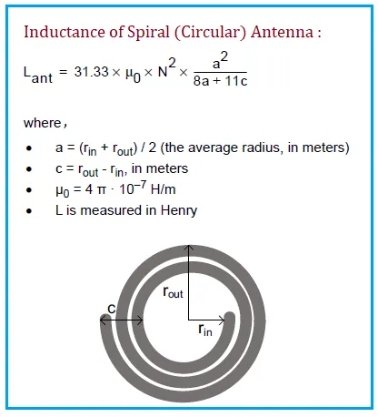 Image Courtesy: ST Microelectronics
This NFC circular antenna calculator is a helpful tool for designing NFC loop antennas.
References
- AN2866 - ST Microelectronics Application Note, “How to design a 13.56 MHz costomized Antenna for ST25 NFC/RFID Tags”, September 2025