NFC Antenna Basics: Design, Testing, and Vendors
Advertisement
Near Field Communication (NFC) operates at 13.56 MHz and relies on magnetic induction between two loop antennas. Unlike far field antennas (like Wi-Fi or Bluetooth) that radiate waves, an NFC system acts like a loosely coupled air core transformer. The reader antenna acts as the primary winding and the tag antenna acts as the secondary winding. Designing these antennas requires a specific approach to inductance matching and Q-factor tuning. This guide covers the essential types, circuits, design steps, and validation methods you need to know.
NFC antennas are widely used in NFC compliant mobiles, NFC payment readers, wallets, ID scanners, data loggers, ticketing systems and various other applications.
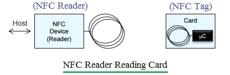
Figure 1: NFC Tag - Reader Communication
NFC Antenna Types and Classes
NFC antennas are almost exclusively inductive loops, but their geometry varies based on the application space and the “Class” definitions set by standardization bodies. Common Geometries are as follows.
- Spiral/Circular: Often used when space allows, offering consistent magnetic field distribution.
- Square/Rectangular: The most common form factor for PCB and inlay designs, maximizing area usage on standard circuit boards.
- Custom Shapes: As seen in wearable technology (like wristbands), antennas can be oval or elongated, though this often reduces efficiency compared to standard shapes.
ISO/IEC 14443 Antenna Classes
According to the NXP Antenna Design Guide (AN11276), antennas are often categorized by size to ensure interoperability:
- Class 1: Large antennas (ISO/IEC 7810 ID-1 card size).
- Class 3: Smaller rectangles (approx. 50x40mm) often found in keyfobs.
- Class 4: Approx. 50x27mm.
- Class 6: Very small (25x20mm), used in space-constrained devices.
NFC Antenna Equivalent Circuit
To design an antenna, you must treat it as an electronic component within an RLC circuit.
- On Tag side, chip has fixed internal tuning capacitance (Ctun). The antenna is modeled as :
- Lant : Inductance of coil traces
- Rant : Resistive losses of copper traces
- Cant : Parasitic capacitance between coil turns
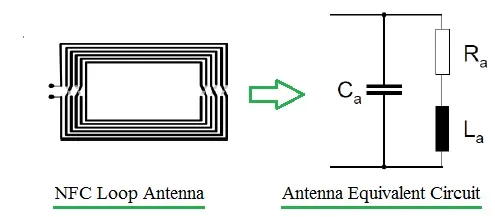
Figure 2: NFC Antenna Equivalent Circuit
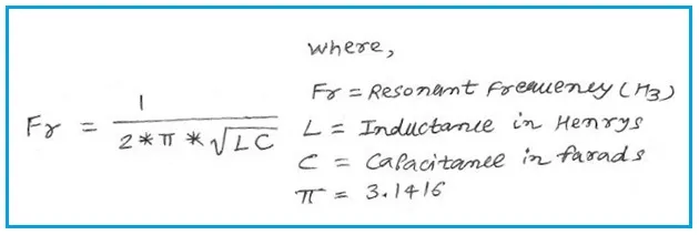
The goal is to form parallel resonant tank circuit where resonant frequency is expressed as follows.
- On reader side, circuit is complex. In addition to reader electronics, it requires antenna, EMC filter and matching network. The EMC component functions as a Low Pass Filter, eliminating second and higher-order harmonics. It also performs impedance transformation. The same is shown in following figure.
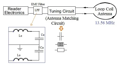
Figure 3: NFC Antenna
NFC Antenna Design Steps (STMicroelectronics Use Case)
Step-1 (Select Chip & determine Capacitance) : First, identify internal tuning capacitance (Ctun) of chosen chip from its datasheet. For example, ST Microelectronics part no. ST25TA02K has Ctun of 50 pF.
Step-2 (Determine Target Inductance) : To resonate ar 13.56 MHz, calculate required inductance. Using resonance formula for 50 pF, we need Lant of approximately 2.75 uH.
Step-3 Calculate Geometry (PCB Layout) : We need to determine number of turns (N), Track Width (w) and spacing (s) to achieve 2.75 uH. You need to use “modified wheeler formula” as per ST Datasheet for squared antenna which is as follows.
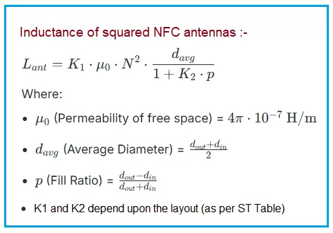
- You can try and vary parameters by using Online NFC Squared Antenna Calculator to determine exact dimensions where you can get 2.75 uH inductance as output.
Step-4 : Create variations with slightly different turns or spacing (e.g. Lnom, Lnom + 5%, Lnom - 5%). Manufacture these prototypes and measure which one hits the frequency sweet spot in the final housing.
NFC Antenna Test Parameters, Equipment and Standards
Once your NFC antenna is printed, you cannot simply rely on a multimeter. It requires specific test and measurement equipments.
Key NFC test parameters
- Inductance (L) : Measured at 13.56 MHz.
- Impedance (Z) : Vector sum of resistance and reactance.
- Resonance frequency (Fres) : The frequency where the parallel impedance is highest (for tags).
- Q-factor : Determines bandwidth. A Q-factor that is too high (narrow bandwidth) blocks the data sidebands. A Q-factor too low reduces power transfer. Target Q is usually between 15 and 30.
NFC Equipments
- Vector Network Analyzer (VNA) : It is used to measure S11 (Reflection Coefficient) and Impedance.
- Impedance Analyzer/ LCR Meter : Useful for measuring bare inductance (L) and Resistance (R).
- Loop Probe (PickUp Coil) : Small turn coil is connected to VNA. Tester can hover this over the tag to measure its resonance frequency “contactlessly” by observing the dip in the signal.
- Oscilloscope : Required for verifying pulse shapes and modulation depth on the reader side.
Standards references
The following standard based tests are performed to check the NFC antenna’s performance:
- ISO/IEC 14443 tests: Tests carried out for PICC/PCD, type-A and type-B for bit rates 106, 212, 424, 848 kbps.
- ISO/IEC 10373-6: Defines test methods and reference PICCs (Proximity Integrated Circuit Cards) used to calibrate readers.
- NFC Forum tests: Defines test cases for NFC Forum devices such as P2P, reader and card modules, used for mobile phones. NFC compliance certification is available and is mandatory for NFC forum devices.
- EMVCo Tests: Tests carried out for PICC/PCD, type-A/B, done only for data rate of 106 kbps.
NFC Manufacturers and Popular Parts
While you often design the antenna trace yourself on a PCB, you need the silicon to drive it. Based on the technical documents, here are the industry leaders and their key components.
- STMicroelectronics: : It manufactures wide range of tag ICs and dynamic tags (tags that connect to a microcontroller via I2C). Popular part numbers include ST25TA series, ST25DV-I2C Series, M24LR / M24SR etc.
- NXP Semiconductors: : It is dominant player in both the reader infrastructure and tag market. Popular parts are PN7160 / PN5180, NTAG 21x Series (213, 215, 216), NTAG I2C Plus etc.
- Texas Instruments: : TI focuses heavily on the reader/writer side, particularly for industrial and automotive applications. Popular parts are TRF7970A, TRF7964A etc.
- The NFC antenna manufacturers are Pulse Electronics, TE Connectivity, AMS AG, Austria, Amphenol MCP, Abracon Corporation etc.
Summary
Designing an NFC antenna is simple and requires precise RLC circuit tuning. By understanding the interaction between your specific chip’s internal capacitance and your PCB coil’s inductance, you can ensure robust communication even in challenging environments.