
nRF24L01 2.4GHz Transceiver: Pinout, Circuit & Uses
Advertisement
nRF24L01 is a 2.4 GHz low power wireless transceiver IC used for short range digital data communication between embedded devices. It combines a 2.4 GHz RF transceiver, packet handling, automatic retransmission, and an SPI interface, making it useful for wireless sensors, remote controls, robotics, automation and microcontroller based communication systems.
Key features of nRF24L01 (as per datasheet)
- Radio Operation: Worldwide 2.4GHz ISM band operation (2.400 to 2.4835GHz) with 126 RF channels.
- Air Data Rates: Supports high speed data rates of 250kbps, 1Mbps, and 2Mbps.
- Ultra-Low Power:
- 11.3mA in TX at 0dBm output power.
- 13.5mA in RX at 2Mbps.
- 900nA in power down mode and 26µA in standby-I mode.
- Enhanced ShockBurst : Hardware baseband protocol engine that handles automatic packet assembly/disassembly, automatic acknowledgment (ACK), and auto retransmission (ART).
- MultiCeiver Technology: Supports 1:6 star networks, allowing six parallel data pipes to receive data simultaneously on a single receiver.
- Power & Interfaces: 1.9V to 3.6V supply range with an on-chip voltage regulator. Host communication is handled via a 4-pin hardware SPI (max 10Mbps) with 5V tolerant inputs.
- Package: Compact 20-pin 4x4mm QFN package.
nRF24L01 Pin Diagram
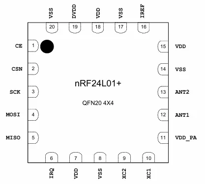
| Pin | Name | Type | Description |
|---|---|---|---|
| 1 | CE | Digital Input | Chip Enable. Activates RX or TX mode. |
| 2 | CSN | Digital Input | SPI Chip Select (Active Low). |
| 3 | SCK | Digital Input | SPI Clock. |
| 4 | MOSI | Digital Input | SPI Slave Data Input. |
| 5 | MISO | Digital Output | SPI Slave Data Output, with tri-state option. |
| 6 | IRQ | Digital Output | Maskable interrupt pin. Active low. |
| 7, 15, 18 | VDD | Power | Power Supply (+1.9V to +3.6V DC). |
| 8, 14, 17, 20 | VSS | Power | Ground (0V). |
| 9 | XC2 | Analog Output | Crystal Pin 2. |
| 10 | XC1 | Analog Input | Crystal Pin 1. |
| 11 | VDD_PA | Power Output | Power Supply Output (+1.8V) for the internal Power Amplifier. |
| 12 | ANT1 | RF | Antenna interface 1. |
| 13 | ANT2 | RF | Antenna interface 2. |
| 16 | IREF | Analog Input | Reference current. Requires a 22kΩ resistor connected to ground. |
| 19 | DVDD | Power Output | Internal digital supply output for de-coupling purposes. |
Example Use Case
Scenario : A manufacturer wants to create a single USB wireless receiver (dongle) that connects simultaneously to a battery powered wireless mouse and a wireless keyboard.
Solution : This can be implemented with nRF24L01+ IC.
Applications of nRF24L01
- Wireless PC Peripherals (Mice, keyboards, remotes, 3-in-1 desktop bundles)
- Advanced Media center remote controls
- VoIP headsets
- Game controllers
- Sports watches and sensors
- RF remote controls for consumer electronics
- Home and commercial automation
- Ultra-low power sensor networks
- Active RFID & Asset tracking systems
- Toys
Summary
nRF24L01 offers an economical and low-power solution for short-range 2.4 GHz wireless data communication. Its integrated packet handling, automatic retransmission, and SPI interface reduce the complexity of microcontroller-based wireless systems.
Continue Learning Frequency Converters : Upconverters & Downconverters
- Up & Down Frequency Converter Design Using Discrete Components
- C-Band RF Transceiver Design For VSAT
- Millimeter Wave Up/Down Converter Design
- DUC vs DDC: Understanding Digital Up-Conversion and Digital Down-Conversion
- RF Mixer Basics Tutorial
- Mixer Isolation: LO, RF, and IF
Continue Learning Wireless Fundamentals & Core Concepts
- Wireless Communication Basics : Key Advantages & Disadvantages
- FDD vs TDD Difference in Wireless Communication
- FDMA Vs. TDMA Vs. CDMA : Key Differences
- Fading Basics and Types in Wireless Communication
- Interference Basics & Types
- Listen Before Talk Wireless Communication
- Wireless Propagation Modes
- Wireless Channel Models
- Wired Vs. Wireless Communication : Key Differences