
Types of Antennas in Wireless Communication : 10-15 Examples with functions
Advertisement
Introduction : Antennas are essential components of every wireless communication system, converting electrical signals into electromagnetic waves for transmission and receiving electromagnetic waves back into electrical signals. Numerous antenna types have been developed to meet specific requirements such as high gain, wide bandwidth, compact size, directional coverage, multiband operation, and polarization control. Understanding the different types of antennas and their functions helps engineers select the most suitable antenna for applications including cellular networks, satellite communication, radar, broadcasting, Wi-Fi, GPS, aerospace, defense, and Internet of Things (IoT) devices.
Fundamental Wire & Basic Antennas
Dipole antenna, folded dipole antenna, monopole antenna and ground plane antenna fall under this category.
1. Dipole Antenna
Antennas radiate effectively when the length of the antenna is directly related to the transmitted signal wavelength. Dipole antennas are available in half-wave or quarter-wavelength sizes. A half-wave dipole antenna, called a doublet, will have a length equal to 1/2 of the wavelength of the operating frequency. Usually, RG-59/U is used for 73 Ohm coax lines, and RG-11/U is used for 75 Ohm lines.
The length of this dipole, , can be approximated as:
The shape of the radiation pattern of the half wave dipole antenna is like a doughnut.
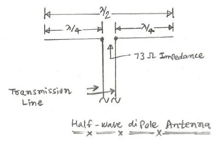
It is widely used as a standalone antenna for basic FM/TV reception or as the core active element (the “driven element”) inside more complex antennas.
2. Folded Dipole Antenna
This is one of the popular types of antennas due to its 300 Ohm impedance. The folded dipole antenna is made of 300 Ohm twin lead, having a length equal to one half wavelength. Their ends are soldered. This is a variation of the standard half wavelength dipole antenna. As shown in the figure, two parallel conductors are connected at the ends, with one side open at the center. This central open part is interfaced with the transmission line.
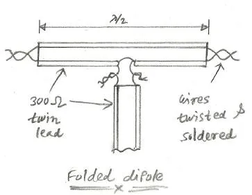
The spacing between conductors is inversely proportional to frequency. For low frequency applications, the spacing is about 2 or 3 inches. For high frequency applications, the spacing is about 1 inch. Commonly used in FM and TV broadcasting.
3. Monopole Antenna
It is essentially half of a dipole. It is a single straight vertical rod or wire mounted over a conductive surface known as a ground plane.
Monopole antenna is used for low frequency and mobile communications. The classic metal “whip” antenna on older cars for AM/FM radio and walkie talkies are monopoles.
4. Ground Plane Antenna
When vertical polarization and an omnidirectional pattern are needed, a ground plane antenna can also be a replacement for a standard half wave dipole antenna. This antenna is fed with a coaxial cable. It is formed by a center conductor connected to the vertical radiator and a shield connected to the earth ground. This generates a vertical omnidirectional radiation pattern.
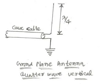
The vertical ground plane antennas are widely used in cars, trucks, boats, and other vehicles. The flat metallic surface of the vehicle acts as a superior ground plane for VHF/UHF antennas. The impedance of this vertical ground plane antenna is about 36.5 Ohm. As no coaxial cable exists at this impedance, a standard 50 Ohm cable is used, which generates a mismatch of about 1.39 SWR.
It is highly effective for VHF/UHF line of sight communications, such as aviation towers and amateur radio.
General Coverage Categories
Omni-directional antenna and directional antenna are placed under this category.
5. Omni-Directional Antenna
It is not a single antenna design, but a broad category of antennas that radiate RF energy equally in a full 360 degree circle on the horizontal plane.
It is used when you need to provide coverage in all directions simultaneously, such as a Wi-Fi router in the center of a house or a central emergency dispatch tower.
6. Directional Antenna
Antennas having an omnidirectional radiation pattern transmit/receive in any direction. In order to send and receive in a particular direction, an antenna with high directivity is required. This type of antenna, having a radiation pattern limited to a narrow horizontal range, is called a directional antenna.
In order to design this kind of antenna, two or more antennas are combined to make an array. This increases gain and directivity. There are two array antenna types viz. parasitic arrays and driven arrays.
It is used to achieve massive range (gain) for point to point wireless links, or to reject interference coming from unwanted directions.
High Gain & Directional Antennas
Yagi-Uda antenna, Log periodic antenna, parabolic reflector antenna and horn antennas are examples of this category.
7. Yagi-Uda Antenna
YAGI antennas were widely used for TV reception, but as they are designed for one frequency only, they are not suited for a wide frequency range. YAGI antennas are made of one driven element, one reflector, and one or more directors. They are made with aluminum tubes and an aluminum cross member.
It is used for long distance point to point links. It is the classic “rooftop TV antenna” and is heavily used in ham radio and specialized long range Wi-Fi setups.
8. Log Periodic Antenna
The benefit of this log periodic antenna is its wide bandwidth application. It is formed by different length driven elements. The longest and shortest elements are half a wavelength long at the lowest and highest frequencies of interest. The elements of this log periodic antenna are fed with transmission line segments.
The phases of the signals sent to different elements are properly set to achieve high directivity and the best gain.
It is highly directional but designed to operate over an incredibly wide range of frequencies (wideband). It is primarily used for TV reception where channels span across large VHF/UHF bands, and in electromagnetic testing labs.
9. Parabolic Reflector Antenna
This parabolic reflector antenna is used in conjunction with a horn antenna, as shown in the figure. It is made of metal or screen mesh. As shown in the figure, during transmission, electromagnetic waves fall onto the wide dish and get radiated into the air, while during reception, electromagnetic waves fall onto the dish and get focused onto the horn antenna.
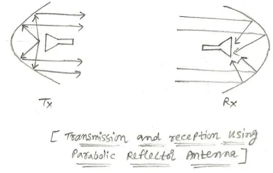
The aperture of the parabola antenna is the area of the outer circle of the parabola. The area is calculated as:
The gain is:
Where is the diameter of the dish antenna and is the wavelength.
It acts like the reflective mirror inside a flashlight, catching RF waves and focusing them into an ultra-narrow, high power beam. Used for satellite communications, radio astronomy, and microwave backhaul links.
10. Horn Antenna
A horn antenna is essentially a flared waveguide. It can work more efficiently when used with a parabolic reflector, as found in dish antennas. Horn antennas are commonly used in satellite and microwave applications. If a normal waveguide is used for transmission of electromagnetic waves, it will not be tightly coupled with free space impedance, resulting in reflected power and standing waves. These mismatches are avoided by flaring the end of the waveguide, which creates the horn antenna. The more gradual the flare, the better the matching and the lesser the losses. This results in greater gain and directivity.
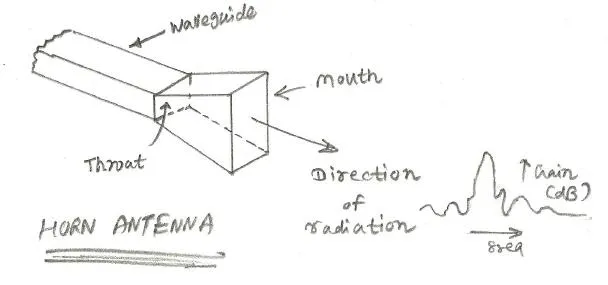
Depending upon the flaring, there are different horn antenna types, including sectoral horns, pyramidal horns, and conical horns. The gain of a pyramidal horn can be summarized as:
Where:
- is approximately 0.5 to 0.6, depending on how the phase/amplitude of electromagnetic fields are displaced across the aperture.
- is the aperture of the horn in square meters.
- is the wavelength in meters.
The horizontal beamwidth of the pyramidal horn can be summarized as:
Where:
- is the beamwidth in degrees.
- is the width of the horn antenna.
- is the wavelength.
Low Profile & Printed Antennas
Microstrip patch antenna, slot antenna and dielectric antenna fall under this category.
11. Microstrip Patch Antenna
This antenna type is made with a microstrip-based design on a PCB. Hence, it is called a microstrip patch antenna. This antenna is basically a circular or rectangular area of copper separated by a conducting ground plane. Between these, there will be an insulating surface.
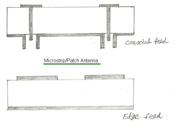
In the case of a rectangular antenna, the width is approximately 1/2 of the wavelength, while in the case of a circular antenna, the diameter is approximately 0.55 to 0.59 of the wavelength.
Function : They are extremely cheap, thin, and lightweight. They are the primary antennas hidden inside modern smartphones, smartwatches, and GPS devices.
12. Slot Antenna
A slot antenna is formed by cutting a metal sheet or waveguide about half a wavelength in size. Due to this cutting of the slot, it is known as a slot antenna. Several slots can also be cut to form a slot antenna array. Slot antennas are widely used in high speed aircraft by filling the slot with insulating material to create a smooth surface. Other external antennas would not be convenient to use at such high speeds.
Function : Because they are completely flat, they can be built flush into the metal skin of aircraft and missiles, providing excellent radar and communications without creating any aerodynamic drag.
13. Dielectric Antenna
Dielectric antennas are made of polystyrene, plastic, or other dielectric materials. These lens antennas are used for millimeter-wave frequencies above 40 GHz.
In this kind of antenna, a dielectric lens is placed over the end of the horn antenna, which focuses waves into a narrower beam. This results in greater gain and directivity.
Function : Used primarily in high frequency microwave and millimeter wave systems. Ceramic dielectric patch antennas are commonly used to shrink the physical size of GPS receivers.
Specialty & Cellular Telecom Antennas
Helical antenna, panel antenna and sector antenna fall under this category.
14. Helical Antenna
As the name suggests, a helical antenna is made of a coil surrounding an insulating support. The diameter of the wire is about 1/3 of the wavelength, and the spacing between turns is about 1/4 of the wavelength. About 6-8 turns are usually used in this type of antenna. A ground plane reflector behind the helix, either circular or square in shape, is used.
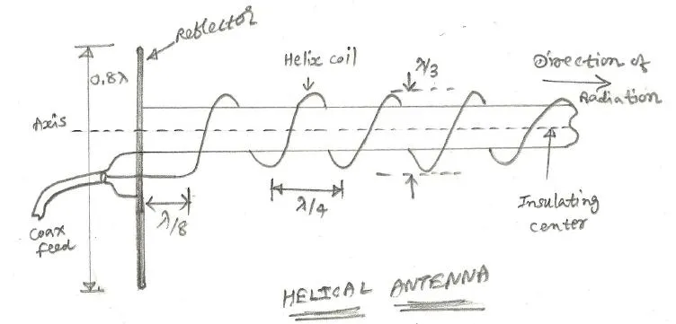
This antenna is widely used in the VHF/UHF range. The gain and beamwidth of this helical antenna are about 12-20 dB and 12-45 degrees, respectively.
15. Panel Antenna
A flat, rectangular directional antenna usually enclosed in a weatherproof plastic/fiberglass shell (radome). Inside, it typically houses an array of patch antennas or dipoles.
Function: Used for high gain, focused outdoor communications, such as connecting two office buildings via a Wi-Fi bridge.
16. Sector Antenna
A specialized, telecom grade panel antenna designed specifically to beam signals across a specific “pie slice” (sector) of a geographic area; usually 60, 90, or 120 degrees wide.
Function: The backbone of cellular networks. By mounting three 120 degree sector antennas on a cell tower, operators provide full 360-degree coverage while dramatically increasing the network capacity compared to a single omni-directional antenna.
Arrays & Next Generation Technologies
Array antenna, phased array antenna, MIMO antenna and massive MIMO antenna are placed under this category.
17. Array Antenna
A system where multiple individual antennas (called elements) are wired together to act as one single, highly powerful antenna.
By combining the signals, an array can achieve much higher gain, longer range, and a narrower beam than any single antenna element could achieve alone.
18. Phased Array Antenna
A phased array antenna is developed using multiple antennas on a common PCB or plane. The antennas used here are patch antennas or dipole antennas in an array. This combination of multiple antennas helps improve gain and directivity.
Individually, all the antennas of the array are controlled, and hence electromagnetic waves can be radiated in different directions as desired.
There are two types of arrangements designed in this type of antenna. In one configuration, all the antennas are fed from a common transmitter or receiver. In the other configuration, a low power transmitter amplifier or LNA is used with each of the array antennas.
Function: By tweaking the timing of the signals, the antenna can steer its RF beam instantly in any direction without physically moving the antenna hardware. Used in fighter jet radars, Starlink satellite terminals, and 5G.
19. MIMO Antenna
A technology utilizing multiple transmitting and receiving antennas on a single device to send multiple distinct data streams over the same frequency simultaneously.
Function: It intentionally uses environmental signal bouncing (multipath) to increase data speeds and reduce dropped connections. It is the core technology behind modern Wi-Fi routers (Wi-Fi 5/6/7/8) and 4G LTE.
20. Massive MIMO Antenna
The evolution of MIMO, packing a massive number of antenna elements (e.g., 64, 128, or even 256) into a single base station panel.
Function: The driving force behind 5G. Massive MIMO allows the cell tower to perform “3D beamforming”; tracking dozens of individual smartphones simultaneously and shooting dedicated, highly focused beams of data directly to them, thereby revolutionizing network capacity and speed.
21. Antenna types used in 6G wireless technology
6G aims to push into the sub-Terahertz and Terahertz bands (100 GHz to 3 THz). Typically antennas used in 6G are ultra-massive MIMO antennas, reconfigurable intelligent surfaces (RIS) or metasurfaces, graphene and plasmonic antennas, antenna-in-package (AiP) or On-Chip Antennas, Lens Antennas (or dielectric lenses) and OAM (Orbital Angular Momentum) Vortex Antennas.
Summary
Each antenna type is designed to satisfy specific performance requirements such as gain, coverage, bandwidth, and frequency range. Choosing the appropriate antenna improves wireless communication efficiency, coverage, and overall system reliability.
Continue Learning About Antenna Technology & Types
- Antenna Basics Tutorial
- Antenna Related Terms
- Antenna mechanical Vs. electrical tilt
- Difference between antenna gain directivity efficiency
- Antenna gain & effective area
- Bandwidth Vs. beamwidth antenna difference
- Antenna Factor
- Near field Vs. Far field antenna radiation pattern
- Cell phone tower antenna basics and types
- Check-out: Guide to List of Antenna Types >>