
Modbus Message Format and Frame Structure
Advertisement
This document explains the Modbus message format, also known as the Modbus frame structure. Modbus is a widely used protocol for industrial automation and metering, and “Modbus” is a trademark of Modicon Inc., the organization that maintains the standard.
The Modbus protocol operates on a query/response model. It’s an application layer protocol built on a client/server architecture, facilitating communication between devices connected on various types of buses or networks.
Modbus commonly runs over RS232, RS422, and RS485 serial interfaces. A Modbus/TCP specification also exists, defining how Modbus frames are transmitted over IP-based networks.
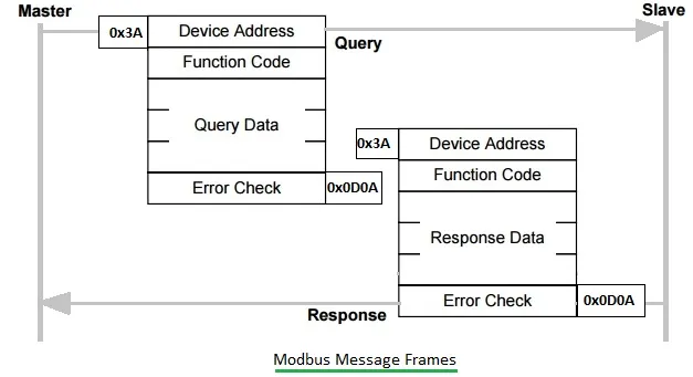
Figure 1: Modbus message format
As illustrated, Modbus employs a master-slave model. A master device initiates transactions (queries), addressing either individual slave devices or broadcasting to all slaves. Slave devices then perform actions based on the received Modbus frame and respond with a “response frame” if necessary. The transmission mode dictates the framing and bit encoding of the messages.
There are two main types of Modbus frame structures: ASCII mode and RTU mode.
Modbus Frame Structure - ASCII Mode
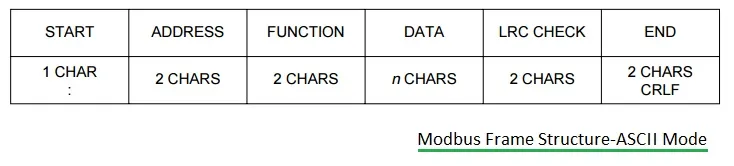
Figure 2: Modbus frame structure - ASCII mode
In ASCII mode, each byte is encoded as two ASCII characters on the serial link. Each ASCII character is transmitted with 1 start bit, 7 data bits, zero or one parity bit, and one or two stop bits.
Modbus Frame Structure in ASCII mode: { Start byte (0x3A), Device Address (2 bytes), Function code (2 bytes), Query Data (variable), Error Check (2 bytes), End Bytes (0x0D0A) }
Modbus Frame Structure - RTU Mode
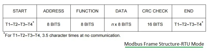
Figure 3: Modbus frame structure - RTU mode
In RTU (Remote Terminal Unit) mode, the message is transmitted as a continuous stream of bytes. Each 8-bit byte is framed by 1 start bit, 8 data bits, 0 or 1 parity bit, and 1 or 2 stop bits. The message begins after a silent period of at least 3.5 character times.
Let’s examine the different fields within the Modbus frame structure.
Modbus Address
The Modbus message starts with an 8-bit target address. This value can range from 0 to 247. The address 0 is reserved for broadcast messages, while the remaining values represent unique device addresses.
Modbus Functions
The function code consists of 2 characters in ASCII mode or 8 bits in RTU mode. It can take any value from 1 to 255, with specific codes selected based on the application profile.
Modbus Data Field
This field carries application-level information as required by the specific Modbus function. If the function involves a variable amount of data, the field typically starts with a “byte count” indicating the size of the data.
Modbus/TCP defines how to access Modbus protocol functionality using TCP/IP.