
J1850 Frame Structure Analysis & Diagnostic Tool
Advertisement
Introduction : The J1850 protocol (PWM/VPW) is a legacy automotive communication standard governing OBD-II diagnostics in older vehicles.
J1850 Frame Structure
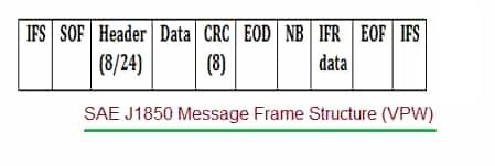
The frame of J1850 contains a Start of Frame, a Header, a Data payload, a Cyclic Redundancy Check (CRC) and an End of Frame.
There are two main variants of J1850 frame viz. VPW (Variable Pulse Width) and PWM (Pulse Width Modulation). The frame structure and key fields define how data is addressed, transmitted and checked for errors.
| Fields | Size | Purpose/Description |
|---|---|---|
| Start of Frame (SoF) | 1 bit time (200 µs for VPW) | A unique pulse/symbol that indicates the beginning of a message. Its unique timing helps all nodes synchronize, high for 200uS |
| Header | 1 or 3 bytes | Contains information about message priority, addressing (source/target), and message type. Defined in SAE J2178. Also check Note-1. |
| Data | 0-12 bytes (PWM) or 0-101 bit times (VPW) | The actual payload of the message. he maximum data length varies by implementation, but is limited by the protocol. |
| CRC | 1 byte | Used for error detection to ensure data integrity during transmission. |
| EOD (End of Data) | 1 bit time (200 µs for VPW) | A symbol that signifies the end of the data by the originator, 200uS low pulse. |
| NB (Normalization Bit) | Row 5, C2 | The NB provides an active separation between the passive EOD symbol and the first data bit of the IFR response. |
| IFR (In Frame Response) | Optional, 1 or more bytes | An optional field where receiving nodes can send a response within the same frame. Used by remote nodes to acknowledge receipt or provide data. |
| End of Frame (EOF) | 1 bit time | A symbol to signify the physical end of the entire frame. Allows synchronization for subsequent messages. |
| Inter Frame Space (IFS) | Variable | A period of bus idle time between frames. |
Note-1:
- Header: Contains priority/type and addressing information. It can be one or three bytes long.
- One Byte Header: Combines priority and address into a single byte.
- Three Byte Header: Separates priority/type (byte 1), target address (byte 2) and source address (byte 3).
J1850 Protocol Data logger tool
In the OSI model, VPW and PWM differ in the physical layer. The key differences between VPW and PWM are as follows.
- VPW : 10.4 kbps bit rate, Bit pulse width = variable, single wire media.
- PWM : 41.6 kbps bit rate, Bit Pulse Width = Constant, Dual wire media.
Following table mentions manufactures or developers of J1850 frame analysis tools.
| Manufacturers | Product/Description |
|---|---|
| IOSiX | OBD-II Data Logger which supports SAE J1850 PWM and VPW, along with ISO 9141, KWP2000 and CAN. |
| Danlaw | DL980QT Data Logger : wireless data logging (vehicle Network Message Data) |
| Cartools (Latvia) | VPWlog – A J1850 VPW data logger |
| Palmer Performance Engineering (PPE) | ScanXL Professional software. |
| Intrepid Systems | WaveBPS tool which supports J1850 |
Summary: A J1850 protocol diagnostic tool gives technicians the capability to capture and analyse frame structures on older vehicle networks, ensuring compatibility, legacy support and comprehensive vehicle diagnostics across generations.
Advertisement


