CAN-FD Bus Frame Analysis & CAN-FD Data Logger Tool
Advertisement
Introduction : The CAN‑FD (Flexible Data Rate) protocol is an enhanced version of CAN. It allows larger payloads (up to 64 bytes) and higher bit rates. It maintains compatibility with traditional CAN bus networks.
CAN-FD Frame Structure
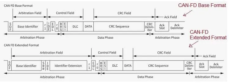
The CAN-FD frame consists of CAN identifier, data length code (DLC), data field, CRC etc. as shown in the figure below. It has added new fields compared to legacy CAN frame. The fields are used to indicate FD mode and optional bit rate switch (BRS) which enables richer communication for advanced automotive systems.
Following are the two frame formats supported by CAN-FD interface.
- FD Base Format : An 11 bit identifier with up to 64 bytes of data.
- FD Extended Format : A 29 bit identifier with up to 64 bytes of data.
Following are the new fields added and existing modified in standard CAN frame to accommodate increased data payload.
- FDF (Flexible Data-Rate Format): This bit indicates whether the frame is a CAN FD frame (recessive) or a classic CAN frame (dominant).
- BRS (Bit Rate Switch): If recessive, this bit signals that the bus will switch to a higher bit rate for the data phase of the transmission; if dominant, the bit rate remains the same as the arbitration phase.
- ESI (Error State Indicator): This bit provides information about the error state of the CAN FD node.
- DLC (Data Length Code): The DLC field is still used, but in CAN FD, it can represent a larger range of data lengths (up to 64 bytes).
CAN-FD Frame Base Format Fields and their usage
| Field | Size | Description |
|---|---|---|
| SOF (Start of Frame) | 1 bit | Indicates the start of a new CAN-FD frame and synchronizes all nodes on the bus. |
| ID (Identifier-11bits) | 11 bits | Arbitration field used for priority. Lower numeric value means higher priority. Identifies the message type. |
| r1/RRS (Reserved bit/Remote Request Substitution) | 1 bit | In Classical CAN this was RTR; in CAN-FD this bit is always dominant (0) and used as a reserved bit. Remote frames are not allowed in CAN-FD. |
| IDE (Identifier extension) | 1 bit | Selects ID length: 0 = 11-bit (base format), 1 = 29-bit (extended format). In our case (i.e. base frame), IDE = 0. |
| EDL/FDF (Extended Data Length/FD Format Bit) | 1 bit | Indicates the frame is a CAN-FD frame. In Classical CAN this field was r0. In CAN-FD, EDL/FDF = 1 means FD format frame. |
| r0/RES (Reserved bit) | 1 bit | Reserved bit; must be transmitted dominant (0) in CAN-FD. Used for protocol compatibility. |
| BRS (Bit Rate Switch) | 1 bit | Enables switching to higher bit rate during data phase. 1 = faster data phase, 0 = same as arbitration phase. |
| ESI (Error State Indicator) | 1 bit | Indicates error status of the transmitting node: 0 = Error Active, 1 = Error Passive. |
| DLC (Data Length Code) | 4 bits | Encodes the length of the DATA field. In CAN-FD, DLC values map to lengths up to 64 bytes. |
| DATA | 0-64 bytes | CAN-FD increases max payload from 8 bytes (Classical CAN) to 64 bytes. |
| CRC_sequence | 17 bits (for 0-16 bytes) or 21 bits (for 20-64 bytes) | Provides error detection over the frame. CAN-FD uses longer CRCs due to increased payload size. |
| CRC_delimiter | 1 bit | Fixed recessive bit that separates CRC from ACK. |
| ACK_slot | 1 bit | During this bit, any receiver that successfully receives the frame pulls the bus dominant to signal acknowledgment. |
| ACK_delimiter | 1 bit | Fixed recessive bit marking end of ACK field. |
| EOF (End of Frame) | 7 bits | Indicates the end of the CAN-FD frame. Must be recessive. |
CAN-FD Extended Frame – Field Size & Usage
| Field | Size | Description |
|---|---|---|
| SOF (Start of Frame) | 1 bit | Marks the beginning of the frame and synchronizes all nodes. Always dominant. |
| ID_Base | 11 bits | The upper 11 bits of the 29-bit identifier. Used for arbitration priority. |
| SRR (Substitute Remote Request) | 1 bit | Must be recessive (1). Used in extended frames to preserve arbitration rules. Replaces the RTR bit from Classical CAN. |
| IDE (Identifier Extension) | 1 bit | 1 = Extended ID (29-bit). Forces extended arbitration format and indicates that ID_ext follows. |
| ID_ext | 18 bits | Lower 18 bits of the 29 bit identifier. Combined with ID_base to form the full 29-bit arbitration ID. |
| r1 (Reserved bit) | 1 bit | Reserved — must be dominant (0) in CAN-FD. |
| EDL (Extended Data Length)/FDF (FD Format Bit) | 1 bit | Set to 1 to indicate a CAN-FD frame (instead of Classical CAN). |
| r0 (Reserved Bit) | 1 bit | Reserved — must be dominant (0) for CAN-FD. |
| BRS (Bit Rate Switch) | 1 bit | 1 = switch to higher bit rate during data phase. 0 = same bit rate as arbitration phase. |
| ESI (Error State Indicator) | 1 bit | Indicates transmitter state: 0 = error active, 1 = error passive. |
| DLC (Data Length Code) | 4 bits | Encodes payload length (0 to 64 bytes). FD DLC values map to extended lengths (e.g., 9 -> 12 bytes, 15 -> 64 bytes). |
| DATA | 0 to 64 bytes | User payload. CAN-FD supports up to 64 byte data fields, unlike CAN’s 8 bytes. |
| CRC_Sequence | 17 bits (payload <= 16 bytes), 21 bits (payload 20-64 bytes) | Checksum used for error detection |
| CRC_delimiter | 1 bit | Fixed recessive bit separating CRC field from ACK field. |
| ACK_slot | 1 bit | Receivers that validated the frame drive this bit dominant to acknowledge correct reception. |
| ACK_delimiter | 1 bit | Fixed recessive bit marking the end of the ACK field. |
| EOF (End of Frame) | 7 bits | Indicates end of CAN-FD frame; must be recessive. |
ClassiC CAN vs CAN-FD Frame : Key differences
CAN_Classic_Frame = {SOF, ID (11 bits), RTR, IDE, r0, DLC, DATA (0 to 8 bytes), …}
CAN_FD_Frame_Base = {SOF, ID (11 bits), r1 or RRS, IDE, EDL or FDF, r0 or res, BRS, ESI, DLC, DATA (0 to 64 bytes), CRC_sequence, CRC_delimiter, ACK_slot, ACK_delimiter}
CAN_FD_Frame_Extended = { SOF, ID_base, SRR, IDE, ID_ext, r1, EDL, r0, BRS, ESI, DLC, DATA (0 to 64 bytes), CRC_sequence, CRC_delimiter, ACK_slot, ACK_delimiter}
Examples
CAN FD Base Format (11 bit identifier used):
ID = 43C, Length of Data = 4 bytes, Same bit rate for arbitration and data phases, transmitter is error active node.
SOF = 0 , Base ID = 10000111100, r1 = 0 , IDE = 0 , EDL - 1, r0 = 0 , BRS = 0, ESI = 0, DLC = 0100, DATA = ___
CAN FD Extended Format (29 bit identifier used):
ID = 10F32456, Length of Data = 4 bytes, Higher Bit Rate for Data Phase, Transmitter is Error Passive Node
SOF = 0, Base ID = 10000111100, SRR = 1, IDE = 1, ID_extension = 110010010001010110, r1 = 0, EDL = 1, r0 = 0, BRS = 1, ESI = 1, DLC = 0100, DATA = ___
CAN-FD Data logger tool
Following table mentions some of the popular data logger tool manufacturers used to analyze CAN-FD protocol frames and their fields.
| Manufacturers | Product with features |
|---|---|
| CSS Electronics | CANedge1 Data Logger: 2 × CAN (or LIN) channels, supports CAN-FD. CANedge2 Data Logger: Likely similar CAN / CAN-FD logging |
| Kvaser AB | Kvaser Memorator Pro 2xHS v2: 2 × CAN channels; CAN-FD compliant up to 8 Mbit/s |
| Waveshare | Waveshare USB‑CAN‑FD‑B Analyzer: |
| Intrepid Control Systems | neoVI FIRE 3 : 16 × CAN-FD channels + 8 LIN + Ethernet |
| G.i.N. GmbH | G.i.N. GL5300 Series : Supports up to 4 × CAN FD channels (in GL5350) |
Summary: A CAN-FD packet data logger becomes indispensable when analysing high speed, high volume frame traffic in modern vehicle networks. These CAN-FD test and measurement tools provide detailed insights into extended payloads and network behaviour that traditional CAN tools cannot easily capture.