
CAN Bus Frame Analysis & CAN Packet Data Logger Tool
Advertisement
Introduction : CAN bus is a foundational communication protocol used in modern vehicles. It enables numerous ECUs (Electronic Control Units) to share critical status/control messages using short and prioritized frames.
CAN Frame Structure
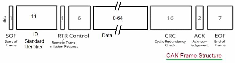
The CAN bus frame uses defined structure as shown in the figure. As it carries different messages, it is also known as message based protocol. It contains SOF (Start of Frame), identifier, control bits, data bytes, CRC, acknowledgement and EOF (end of frame). CAN frame allows deterministic communication and fault detection. CAN bus has two wires (CAN_H and CAN_L), referred as twisted pair.
There are two states of CAN bus viz. IDLE and Data transfer phase. When there is no transmission of frame on the CAN bus, state is called IDLE state. In this IDLE state, bus carries recessive bit (i.e. logic 1).
| Field | Size | Description |
|---|---|---|
| SOF (Start of Frame) | 1 bit | Every CAN frame starts with dominant bit i.e. logic-0. Transmitting node with SOF indicates that bus is not idle and informs all the other receiving nodes to synchronize with its frame. |
| ID (Identifier) | 11 bits | There are different frame types and they are identified by message ID. In message ID, bit numbers 4th and 11th are masked for some reasons and rest of the 9 bits indicate unique message ID. Due to this, there are 2^9 (i.e. 512) CAN frames in single network. Message ID can be represented in hexadecimal from 000 to 7FF. |
| RTR (Remote Transmission Request) | 1 bit | It indicates whether node itself is transmitting or requesting other node to transmit. RTR of ‘0’ means data frame where as RTR of ‘1’ means remote frame. |
| Control | 6 bits (2 bits reserved, 4 bits DLC) | The reserved bits (R0, R1) are initially planned for future use. Now-a-days they are used in latest CAN standards such as R1 is used as IDE but which differentiates between standard and extended frame types. R0 is used as FDF bit which differentiates between CAN and CAN-FD frame types. DLC (Data Length Code) is 4 bits in size and range from 0 to 8 which allows data with up to 8 bytes in length. |
| Data | Variable, 0 to 64 bits | Length of this data is indicates by DLC field. This field can contain 0 to 8 bytes. |
| CRC | 16 bits (15 bits actual CRC and 1 bit CRC delimiter) | CRC refers to Cyclic Redundancy Check which is used for error detection. Transmitting node inserts this after checksum computation. At the receiver node, checksum is again calculated and it is compared with the value of the CRC received in this field. If re-calculated value at receiver matches with the one received, frame is valid else frame is invalid. CRC delimiter is always logic-1. This time period (equivalent to a bit ) allows receiver to validate the received frame. |
| Acknowledgement (ACK) | 2 bits (1 bit ack and 1 bit ACK Delimiter) | Transmitting node inserts logic ‘1’ in this slot. All the receiving nodes replaces this slot with logic ‘0’ when the frame is successfully received and valid. When this field it not changed by the receiving node, it means there is “ack error”. ACK delimiter field contains recessive bit. |
| EOF (End of Frame) | 7 bits | It contains 7 consecutive recessive bits (i.e. logic-1), which indicates end of the frame. |
| Intermission or Interframe Space (IFS) | 3 bits | These are interframe spacing bits. These bits signify end of frame (EOF) and bus is returning to IDLE state. |
-
There are four different kinds of frames in CAN protocol. These include data frame, error frame, remote frame and overload frame.
-
CAN_Standard_Frame : {SOF, ID, RTR, R0, R1, DLC, Data, CRC, ACK, EOF, IFS }
What are dominant bit and recessive bit?
In CAN protocol, dominant bit corresponds to logic value of zero (‘0’) and recessive bit corresponds to logic value of one (‘1’). Dominant bit is used in SOF bit and RTR bit in data frame. Recessive bit is used in idle bus state and RTR bit in remote frames. Bus state in dominant bit is actively driven and overwrites recessive bit. Bus state in recessive bit is passively returned to idle state.
CAN-Extended Frame Format
- CAN_Extended_Frame : {SOF, ID_1, SRR, IDE, ID_2, RTR, R0, R1, DLC, Data, CRC, ACK, EOF, IFS }
- As mentioned, identifier is of size 29 bits total, which is divided into two parts ID_1 (11 bits) and ID_2 (18 bits). Here ID_1 is same as ID used in Standard CAN Frame.
- In the place of RTR used in standard frame, extended frame used SRR (Substitute Remote Request), which is always single bit in size and it uses value of logic-1.
- Following SRR bit, reserved bit ‘R1’ is used as IDE (Identifier Extension). This IDE bit indicates whether the frame is standard or extended. IDE of value logic-0 indicates standard frame where as IDE of value logic-1 indicates extended frame. IDE bit is very critical to determine whether the frame is standard or extended.
EXAMPLES
CAN Base Format Example :
- ID = 43C, Length of Data = 4 bytes
- SOF = 0, Base_ID = 10000111100, RTR = 0 , r1 = 0, r0 = 0, DLC = 0100, DATA = ____
CAN Extended Format Example :
- ID = 10F32456, Length of Data = 4 bytes
- SOF = 0, Base_ID = 10000111100, SRR = 1, IDE = 1, ID Extension = 110010010001010110, RTR = 0, r1 = 0, r0 = 0, DLC = 0100, DATA = ___
CAN Packet Data logger tool
Following table mentions some of the popular data logger tool manufacturers used to analyze CAN bus protocol frames and their fields.
| Manufacturers | Product with features |
|---|---|
| CSS Electronics, Denmark | CANedge 2 CAN Bus Data Logger : Supports traditional CAN and CAN-FD frames. 8 GB SD card for data logging for longer duration. It allows connection with remote cloud server using wi-fi for data uploading. CANedge 1 CAN Bus Data Logger : Supports two channels i.e. classical CAN and LIN and houses 8 GB SD card. |
| ICP DAS CO., LTD | Product CAN-Logger100 Supports CAN 2.0A and 2.0B. |
| Kvaser, Sweden | Memorator Professional HS/LS : Supports both 11-bit (as per CAN 2.0A) and 29-bit (as per CAN 2.0B) identifiers. |
| ZD Technology, Germany & China | ZD DataGrabber : Can support CAN, CAN-FD and LIN bus protocols and their analysis. |
Summary: By leveraging a dedicated CAN packet data logger tool, engineers and diagnosticians can decode, visualize and archive CAN frame traffic. It facilitates faster fault isolation, performance tuning and validation of network behavior.
Advertisement


