 RF
RFTransmission Line Calculator & Formula : Reflection coefficient, SWR
Advertisement
A transmission line is a specialized structure used to transfer electrical energy or signals from one point to another with minimal distortion and loss. Unlike ordinary circuit wires, transmission lines exhibit distributed electrical properties (resistance, inductance, capacitance, and conductance) along their length, which significantly affect signal propagation when the line length is comparable to the signal wavelength.
Transmission line theory provides the mathematical framework to analyze voltage and current variations along the line, reflections caused by impedance mismatch, power transfer efficiency, and signal integrity. It is widely applied in radio-frequency (RF) systems, microwave engineering, antennas, high speed digital circuits, and power systems. This page covers transmission line calculator which takes characteristic impedance and load impedance as inputs and provides reflection coefficient (magnitude & phase) at load as well as at certain wavelength.
EXAMPLE:
INPUTS:
- Characteristic Impedance = 100 Ohm
- Load Impedance (Real) = 40
- Load Impedance (Imaginary) = 70
- Line Length in terms of Wavelength = 0.3 λ
OUTPUTS:
Reflection Coefficient at Load :
- Gamma_L = -0.1429 + j 0.5714
- |Gamma_L| = 0.589
- Phase(Gamma_L) = 104.03 Degrees
- VSWR = 3.86
- Return Loss = 4.59 dB
- Power Reflected = 34.69 %
Reflection Coefficient at Length of 0.3 λ:
- Phase Shift = -216 Degrees
- | Gamma (l) | = 0.589
- VSWR = 3.86
Assumption:
- Characteristic Impedance is real for lossless lines.
Transmission Line Formula
Transmission line theory models a line as a distributed network of infinitesimal circuit elements characterized by parameters R, L, G and C per unit length. These parameters lead to wave propagation described by the telegrapher’s equations, which yield traveling voltage and current waves along the line.
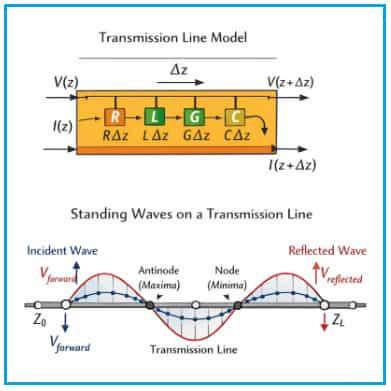
A key parameter is the characteristic impedance (Z0), defined as the ratio of voltage to current for a wave traveling along an infinitely long line. When the load impedance equals Z0 , no reflections occur and maximum power is delivered. If the load differs from Z0, part of the signal reflects back toward the source, quantified by the reflection coefficient and Voltage Standing Wave Ratio (VSWR).
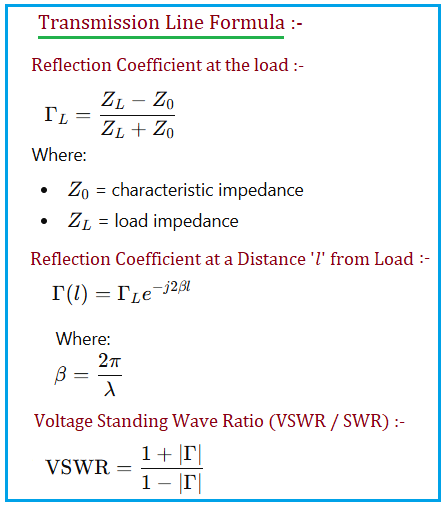
Following transmission line formula are used in this calculator. It covers reflection coefficient (Gamma), SWR (Standing Wave Ratio), return loss and power.
Transmission line theory is essential for designing impedance matching networks, minimizing signal reflections, ensuring efficient power transfer, and maintaining signal integrity in high-frequency and high-speed systems.
Summary:
- The magnitude of Γ does not change with line length (lossless line)
- Only the phase of Γ changes along the line; Only the phase rotates by -2βl
- SWR does NOT depend on line length (for lossless lines) and VSWR depends only on |Γ|. (Check VSWR is same at load ZL and at length of 0.3 λ )
References for further study
Text Books :
- D. M. Pozar - Microwave Engineering (4th Ed.); Sections: Transmission Lines, Reflection Coefficient, VSWR
- Concepts and Applications of Microwave Engineering By Sanjay Kumar and Saurabh Shukla
- Collin - Foundations for Microwave Engineering
Standard Engineering References :
- ARRL Antenna Handbook (Transmission Line chapter)
Advertisement


