
Transmission Impairment Types: Effects & Mitigation in Digital Data
Advertisement
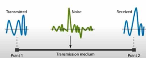
Introduction : Digital communication system consists of transmitter, receiver and channel. If the data is analog, it needs to be converted to digital form using ADC (Analog to Digital Converter) or vice versa as per medium requirement (wired, wireless, optical). The digital data goes through various impairments before it reaches the receiver end. The common impairments across the transmission include attenuation, delay, latency, jitter, dispersion, distortion, crosstalk, echo etc. These impairments degrade signal quality which lead to bit errors, loss of synchronization and reduced data integrity. This article covers major impairments, their effect on digital data signal and proven mitigation/correction methods to preserve signal fidelity and reliability.
Types of impairments in digital data transmission
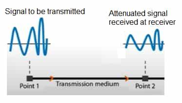
- Attenuation:
It is the gradual loss of signal strength (amplitude) as it travels through a transmission medium due to resistance, absorption, or scattering.
- Effect on digital data : Due to attenuation, signal amplitude decreases which makes it difficult for receiver to distinguish between logical ‘0’ and ‘1’. As a result, it causes bit errors.
- Mitigation/Correction techniques : There many techniques used to compensate for attenuation of signal. The most common are use of amplifiers or repeaters for digital signals.
- Delay & latency:
There are different types of delay involved when data packet or signal travel through the medium between sender and receiver.
-
Propagation delay : Time for signal to go from source to destination.
-
Transmission delay : Time to push the bits onto the network.
-
Processing delay : Time for network devices to process and forward data.
-
Queueing delay : Time a packet spends waiting in a queue before it is transmitted.
-
Latency is the sum of different types of delays which include propagation, transmission, processing and queueing related delays.
-
Effect on data : It causes slower response times in networks, leads to overrun/underrun of buffer, reduced throughput, timing errors in synchronous systems.
-
Mitigation techniques : Minimize processing overhead and network congestion, use buffering to absorb variable delay etc.
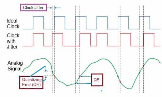
- Jitter:
It is the variation in the time delay of received signals, often caused by network congestion, timing drift or electromagnetic interference.
- Effect on data : Causes bit timing errors & packet misordering
- Mitigation techniques : Employ PLLs (Phase Locked Loops) for clock recovery, use time stamping and sequencing protocols such as RTP for VoIP etc.
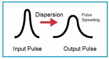
- Dispersion:
It occurs when different frequency components of a signal travel at different speeds, causing the pulse to spread over time. In optical fiber there are different types of dispersion such as chromatic, modal, and polarization dispersion.
- Effect on data : Causes Inter Symbol Interference (ISI), degrades signal integrity and increases bit error rate (BER).
- Mitigation techniques : Use dispersion-compensating fiber, apply equalization techniques such as adaptive equalizers, employ coherent detection and DSP algorithms for compensation, use fiber Bragg gratings in optical systems etc.
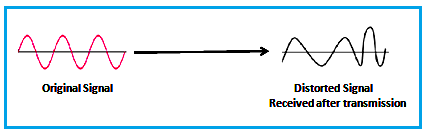
- Distortion:
It occurs when the shape of the signal waveform is altered, usually due to the nonlinearity of medium or frequency response variation across channel.
- Effect on data : Causes signal deformation, leading to misinterpretation of bits.
- Mitigation techniques : Use linear amplifiers and avoid overdriving circuits, Implement equalizers to correct frequency response etc.
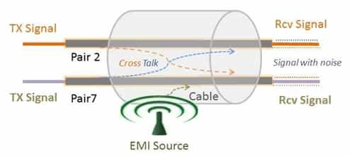
- Crosstalk:
It is unwanted coupling between signal paths, where a signal from one channel interferes with another. It can be near end crosstalk or far end crosstalk.
- Effect on data : Produces random errors and noise in adjacent channels, reduces SNR (Signal to Noise Ratio).
- Mitigation techniques : Maintain proper spacing and grounding, Use differential signaling in USB & ethernet, Use twisted pair or shielded cables etc.
- Echo:
It occurs when a portion of the transmitted signal is reflected back to the source due to impedance mismatches or open circuits in the medium.
- Effect on data : It causes interference with original signal due to its delayed version, leads to ISI and bit timing errors etc.
- Mitigation techniques : Use echo cancellers in telecom systems, Ensure proper impedance matching in all terminations, use adaptive filters for echo suppression etc.
- Noise:
It introduces random or unwanted signals that interfere with data integrity.
- Thermal Noise (White Noise) : Random motion of electrons in conductors due to temperature. It is present in all electronic components.
- Impulse Noise : Sudden, short duration spikes. It is caused due to switching or lightning or power line interference or faulty equipment.
- Intermodulation Noise : Mixing of multiple signals in nonlinear devices such as amplifier or mixer.
- Quantization Noise : Error introduced during analog to digital conversion (ADC) due to finite resolution.
- Shot Noise : Random fluctuations due to discrete charge carriers. Common in semiconductor devices, photodiodes and optical detectors.
- Phase Noise : Random fluctuations in the phase of the carrier signal. Typically arising from oscillator instability or jitter in clock circuits.
- Synchronization related impairments:
Following are the impairments related to timing and clock synchronization.
- Clock drift (or frequency offset) : It occurs when the transmitter’s clock and the receiver’s clock run at slightly different rates (i.e. frequencies). Over time, these small mismatches accumulate.
- Bit slip (or clock slip) : It is the insertion or deletion of a bit in the received stream due to clock misalignment or synchronization errors.
- Frame slip : It happens when the receiver loses alignment of the frame boundary (i.e. which bits correspond to the start of a frame).
Frequency domain measurement
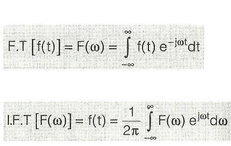
- As we know, each time domain waveforms can be converted to frequency domain waveforms. This is obtained by taking the Fourier Transform of the time domain signal.
- Time domain signal is represented in terms of its frequency components i.e., how much of each frequency is present in the signal.
- The frequency domain representation of time domain signal is important because it gives insight into what’s inside the signal and how systems affect those frequencies, making analysis, design and processing much simpler and more powerful. It helps us see patterns and periodicities not obvious in time.
- Often inverse fourier tranform is also carried out for analysis using mathematical algorithms.
-
There are different set of tools and applications developed to generate and analyze frequency domain signals. The common tools are spectrum analyzer, vector signal generator (VSG) and vector signal analyzer (VSA).
-
Like time domain, there are various measurements to be performed in frequency domain too. It include power spectrum or Power Spectral Density (PSD), Intermodulation distortion (Third Order Intercept Point-TOI) or harmonic distortion, spurious, 1dB compression point, Phase noise, Error Vector Magnitude (EVM), Frequency accuracy, Gain etc.
-
The receiver side measurements include Sensitivity, selectivity (or Adjacent Channel Rejection-ACR), dynamic range, noise figure, image frequency rejection etc.
Measurements Techniques and tools
There are various tools or equipments used for the measurements of digital communication signals (modulated & unmodulated). They are used to identify & quantify various time domian impairments described above. These equipments help engineers to locate the issue and helps in applying appropriate correction techniques. The tools include oscilloscope, Time domain reflectometer, Bit Error Rate (BER) Tester, digital communication analyzers (DCAs), High-Bandwidth Digitizers, VSAs, Spectrum Analyzer etc.
Conclusion: Test and measurement (T&M) equipments are very useful to analyze modulated and unmodulated time domain waveforms. With the help of these T&M equipments, engineers can not only detect impairments but also pinpoint where, how much and why they occur. This diagnostic insight is essential to fine tune mitigation or correction methods to deliver reliable & high fidelity digital communication.
Tags
Advertisement


