 RF
RFLTE PDCCH: Physical Downlink Control Channel Explained
Advertisement
This page describes the LTE PDCCH channel, or Physical Downlink Control Channel, within the LTE system. It’s used to carry DCI (Downlink Control Information).
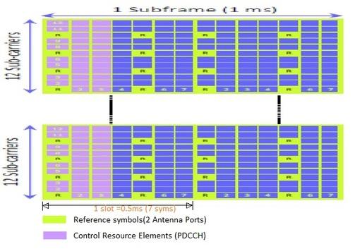
We obtain information about the number of OFDMA symbols used by the PDCCH after decoding the PCFICH. These symbols are always located at the start of each subframe. The Resource Elements (REs) allocated to the PDCCH are grouped into sets of 4 REs, referred to as quadruplets.
These RE quadruplets are further grouped into CCEs (Control Channel Elements). One CCE contains 9 quadruplets, resulting in 36 REs per CCE. The PDCCH uses QPSK modulation, providing a CCE capacity of approximately 72 bits.
There are a total of 4 PDCCH formats, as described in 3GPP TS 36.211. The following table summarizes these formats:
Table 1: LTE PDCCH channel formats
| PDCCH Format | Number of CCE | Number of RE Quadruplets | Number of Bits |
|---|---|---|---|
| 0 | 1 | 9 | 72 |
| 1 | 2 | 18 | 144 |
| 2 | 4 | 36 | 288 |
| 3 | 8 | 72 | 576 |
The appropriate PDCCH format is selected based on the required size of the DCI. A 16-bit CRC is attached to the DCI bits prior to rate-1/3 channel coding and rate matching.
Table 2 shows the coding rate for each DCI and PDCCH format:
Table 2: Coding rates for each DCI and LTE PDCCH format (BW-5,10,15MHz)
| Coding Rate | DCI Format | Channel Bandwidth | DCI Bits after CRC | PDCCH Format 0 | PDCCH Format 1 | PDCCH Format 2 | PDCCH Format 3 |
|---|---|---|---|---|---|---|---|
| DCI-0,1A,3,3A | 5 | 41 | 0.57 | 0.28 | 0.14 | 0.07 | |
| 10 | 43 | 0.60 | 0.30 | 0.15 | 0.07 | ||
| 20 | 44 | 0.61 | 0.31 | 0.15 | 0.08 | ||
| DCI-1 | 5 | 43 | 0.60 | 0.30 | 0.15 | 0.07 | |
| 10 | 47 | 0.65 | 0.33 | 0.16 | 0.08 | ||
| 20 | 55 | 0.76 | 0.38 | 0.19 | 0.10 | ||
| DCI-1B | 5 | 43 | 0.60 | 0.30 | 0.15 | 0.07 | |
| 10 | 44 | 0.61 | 0.31 | 0.15 | 0.08 | ||
| 20 | 46 | 0.64 | 0.32 | 0.16 | 0.08 | ||
| DCI-1C | 5 | 28 | 0.39 | 0.19 | 0.10 | 0.05 | |
| 10 | 29 | 0.40 | 0.20 | 0.10 | 0.05 | ||
| 20 | 31 | 0.43 | 0.22 | 0.11 | 0.05 | ||
| DCI-1D | 5 | 43 | 0.60 | 0.30 | 0.15 | 0.07 | |
| 10 | 44 | 0.61 | 0.31 | 0.15 | 0.08 | ||
| 20 | 46 | 0.64 | 0.32 | 0.16 | 0.08 | ||
| DCI-2 | 5 | 55 | 0.76 | 0.38 | 0.19 | 0.10 | |
| 10 | 59 | 0.82 | 0.41 | 0.20 | 0.10 | ||
| 20 | 67 | 0.93 | 0.47 | 0.23 | 0.12 | ||
| DCI-2A | 5 | 52 | 0.72 | 0.36 | 0.18 | 0.09 | |
| 10 | 57 | 0.79 | 0.40 | 0.20 | 0.10 | ||
| 20 | 64 | 0.89 | 0.44 | 0.22 | 0.11 |
Coding rate = number of DCI bits after CRC attachment / Capacity of PDCCH.
The number of CCEs depends on the channel bandwidth and the number of OFDMA symbols allocated for the PDCCH. Table 3 presents this relationship, assuming no quadruplets are allocated to PHICH and 4x4 MIMO is not used.
Table 3: Maximum no. of CCE (Assuming 1 or 2 transmit antenna ports)
| Channel BW | OFDMA symbols for PDCCH | | ---------- | ----------------------- | ----- | ----- | ------ | ------ | ------ | | | 1.4 MHz | 3 MHz | 5 MHz | 10 MHz | 15 MHz | 20 MHz | | 1 | - | 2 | 5 | 10 | 16 | 21 | | 2 | 2 | 7 | 13 | 27 | 41 | 55 | | 3 | 4 | 12 | 21 | 44 | 66 | 88 | | 4 | 6 | - | - | - | - | - |
In summary:
- This channel informs the UE about the resource allocation of PCH and DL-SCH.
- It indicates the modulation, coding, and hybrid-ARQ information related to DL-SCH.
- Generally, a maximum of three or four OFDM symbols can be used for PDCCH.
- The information carried on the PDCCH is referred to as Downlink Control Information (DCI).
- Uses QPSK modulation.
LTE PDCCH Channel REFERENCE: 3GPP TS 36.211
Advertisement


