
Whiskbroom vs Pushbroom Sensors: Key Differences Explained
Advertisement
This article compares Whiskbroom and Pushbroom sensors, outlining the key differences between these scanner types used in remote sensing.
Whiskbroom Sensor
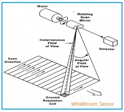
Figure 1: Whiskbroom Sensor
The Whiskbroom sensor, as shown in Figure 1, utilizes a linear or area array of detectors. The image is constructed through the satellite’s movement along its orbital track and by cross-track scanning using a mirror.
Example: LANDSAT MSS/TM
The cross-track scanner employs a “back and forth” motion of the fore-optics, scanning each ground resolution cell individually. The Instantaneous Field of View (IFOV) of the instrument determines the pixel size.
Pushbroom Sensor
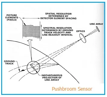
Figure 2: Pushbroom Sensor
Figure 2 illustrates the Pushbroom sensor, also known as an along-track scanner. This type of sensor uses a linear array of detectors aligned cross-track.
Here, reflected radiance passes through a lens and onto a line of detectors, eliminating the need for a scanning mirror. The image is constructed by the satellite’s movement along its orbital track.
Example: SPOT HRV (High Resolution Visible)
In this sensor type, an area array can also be used for multi-spectral remote sensing. Dispersion is used to split light into narrow spectral bands and direct it to individual detectors.
Comparison Table: Whiskbroom Sensor vs. Pushbroom Sensor
| Feature | Whiskbroom Sensor | Pushbroom Sensor |
|---|---|---|
| Swath Width | Wide | Narrow |
| Mechanical System | Complex | Simple |
| Optical System | Simple | Complex |
| Components | Filters and sensors | Dispersion grating & CCDs |
| Dwell Time | Shorter | Longer |
| Pixel Distortion | Yes | No |