UWB Frequency Stitching: Intra vs Inter Packet Explained
Advertisement
Introduction : Regulatory limits often restrict the contiguous bandwidth available to a single device. The IEEE 802.15.4ab standard solves this with a groundbreaking technique called Frequency Stitching. By combining multiple smaller channels, devices can emulate a massive bandwidth for specific application such as high definition radar sensing.
In radar and sensing, resolution is directly proportional to bandwidth. The wider the bandwidth, the finer the detail you can capture. To achieve high definition sensing without needing impossibly wide contiguous channels, the new standard introduces a clever technique to “stitch” together multiple frequency bands. This is done in two distinct ways viz. Intra-packet and Inter-packet stitching. Here is how they differ and why it matters for the future of UWB.
Intra-Packet Frequency Stitching
- In this mode, Frequency hopping occurs inside a single data packet.
- In this type, single UWB packet is divided into multiple sensing segments.
- When device transmits this single packet, it hops carrier frequencies for each segment.
- Example: first segment is transmitted on channel-79, the next on channel 78, and third on channel 77, all within one continuous transmission burst.
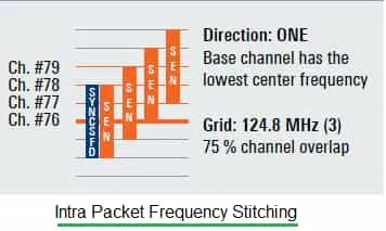 Image Courtesy : Rohde & Schwarz
Inter-Packet Frequency Stitching
- It takes sequential approach in which frequency remains constant for the duration of entire packet. The “stitching” happens over series of packets.
- Example: The device transmits packet-A on channel 79, it then retunes and transmits packet-B on channel 77. The receiver captures these separate instances and stitches the data together in post-processing to form a complete, high resolution picture of the environment.
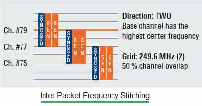 Image Courtesy : Rohde & Schwarz
Key Differences
Following table compares both the methods and mentions their benefits and limitations.
| Feature | Intra-Packet Stitching | Inter-Packet Stitching |
|---|---|---|
| Switching timing | Frequency changes within the packet (i.e. between segments). | Frequency changes between packets (packet to packet). |
| Transmission Structure | Segments of a single packet are sent on different channels. | All segments in one packet are on the same channel; subsequent packets use different channels. |
| Channel Overlap | Typically uses a tighter grid (e.g. 75% overlap, 124.8 MHz steps). | Typically uses a wider grid (e.g., 50% overlap, 249.6 MHz steps) |
| Direction | Often unidirectional (e.g. sweeping from low to high frequency). | Can be configured bidirectionally or focused on specific bands. |
| Latency | Low as it gathers full spectral data in a single transmission timeframe. | Higher as it requires multiple transmission slots to build the full data set. |
| Complexity | High: Requires fast frequency settling times within the packet structure. | Moderate: Allows time for the synthesizer to settle between packets. |
Summary: Both methods share the same ultimate goal: to emulate a massive bandwidth (e.g. 1 GHz or more) using smaller, manageable channels (like 500 MHz). By stitching these frequencies together, 802.15.4ab devices will be able to detect presence, gestures and vital signs with a level of accuracy that previous UWB generations could not achieve.