
What is RF Isolator : Selection Guide Based on Specifications
Advertisement
An RF isolator is a directional component used to protect transmitters from reflected signals. When selecting an RF isolator, critical specifications must be evaluated to ensure system reliability. A comprehensive selection guide involves analyzing the operating frequency range, insertion loss, isolation level (in dB), Voltage Standing Wave Ratio (VSWR) and maximum power handling capability under continuous and peak loads.
How RF Isolator works
The isolator is a two-port device that allows a signal to pass in only one direction, effectively blocking signals traveling in the opposite direction. As shown in Figure 1, signals can travel from port 1 to port 2 with minimal disruption. This ensures that any device connected to port 1 is shielded from reflections originating from port 2.
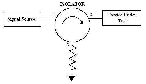
Figure 1: RF Isolator Function
RF Isolator Selection Guide
When selecting an RF isolator, consider the following guidelines:
- Frequency Range: Ensure the isolator operates within the frequency range required for your application.
- Isolation: Look for the highest possible isolation value (from port 2 to port 1) to minimize signal leakage.
- Insertion Loss: Aim for the lowest possible insertion loss to maximize signal transmission efficiency.
- VSWR (Voltage Standing Wave Ratio): A lower VSWR indicates a better impedance match. Choose an isolator with a low VSWR. VSWR is measured as a ratio.
- Mechanical Parameters: Consider factors like isolator size, package type (drop-in, connectorized), and connector types at the ports.
Refer to Table 1 for other important specifications to consider when choosing an RF isolator.
RF Isolator Specifications
The table below outlines the technical specifications of a typical RF isolator.
Table 1: RF Isolator Specifications
| Description | Details |
|---|---|
| Frequency Range | The range of frequencies over which the RF isolator is effective. |
| Insertion Loss | The amount of energy lost during signal transfer from input port 1 to output port 2. Lower insertion loss is desirable. It is expressed by , where and are the input and output powers respectively. |
| Isolation | The measure of how well the isolator prevents signal transmission from output port 2 to input port 1. Higher isolation is desirable. Typical values range from 20 to 25 dB. |
| VSWR | Voltage Standing Wave Ratio. The ratio of maximum voltage to minimum voltage due to impedance mismatch. A VSWR of 1.1:1 is generally better than 1.3:1. |
| Power Handling | The maximum power the isolator can handle without degrading its performance. |
| Group Delay | The time it takes for a signal to travel from input port 1 to output port 2. Expressed in picoseconds or nanoseconds. |
| Package Type | Options include: • Drop-in package • Surface mount package • Connectorized package |
| Type of Connectors | Common connector types include SMA and Coaxial N-type. |
Summary
Carefully evaluating technical specifications like insertion loss and power handling is essential for choosing the optimal RF isolator for your network. Proper selection guarantees maximum protection for expensive microwave transmitters against damaging reverse signal reflections.
Continue Learning RF Isolators : Types & Use Cases
- RF Isolator Types, Functions & Design
- RF Isolator Selection Guide
- Microwave Isolators: Unidirectional Signal Transmission
- Cryogenic Isolator Benefits and Manufacturers