
RF Control Loops : ALC, AGC, PLL, DPD, Open Loop Power Control, IQ offset, Adaptive Beamforming
Advertisement
RF control loops are essential for maintaining signal quality, power accuracy, frequency stability and transmission efficiency in modern wireless systems. Let us understand their working operation and applications in wireless communication.
Open-Loop Power Control
Working Operation: This is the simplest form of control because it lacks a feedback mechanism. A digital command (via a Digital to Analog Converter, or DAC) sets a specific bias or drive level for the RF Power Amplifier (PA). The system assumes that applying “Level X” at the input will result in “Power Y” at the antenna. It does not measure the actual output to verify accuracy.
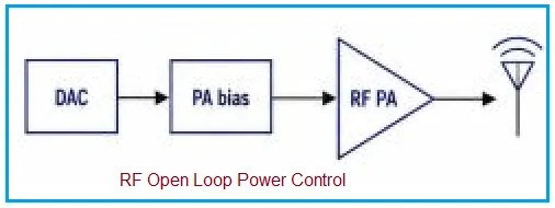
Application: Used in simple, low-cost Fixed Power Transmitters where precise power accuracy is not critical. It is suitable for basic telemetry devices or short range systems where minor fluctuations in output power due to temperature or component aging are acceptable.
- For deeper understanding, refer Open Loop and Closed Loop Power Control Techniques
Automatic Level Control (ALC)
Working Operation: ALC is a closed-loop system designed to keep a transmitter’s output power strictly constant. A directional coupler continuously samples a small fraction of the RF output signal. A detector converts this RF sample into a DC voltage representing the actual output power. This measured level is compared against a desired “Setpoint.” If the output power is too high, the ALC controller reduces the gain of an upstream amplifier; if it is too low, it increases the gain.
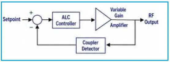
Application: Used primarily in transmitters requiring Constant RF Output Power. This prevents the transmitter from exceeding regulatory limits or damaging its own components, regardless of input signal variations or temperature drift (e.g., broadcast transmitters, cellular base stations).
Automatic Gain Control (AGC)
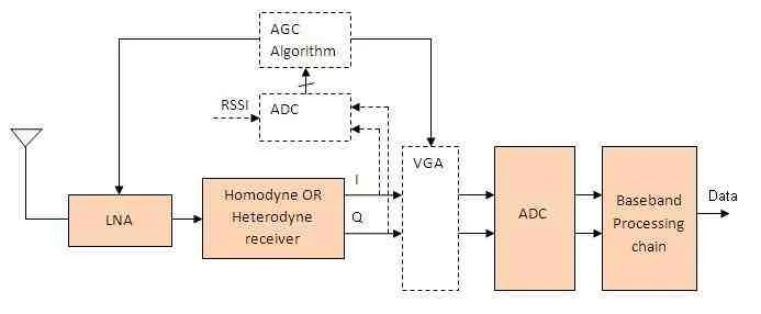
Working Operation: While ALC is for transmitters, AGC is the equivalent closed loop system for receivers. An antenna picks up signals that can vary wildly in strength (from very weak distant signals to very strong nearby signals). An AGC circuit monitors the signal level after it has been amplified. If the incoming signal is too strong, the AGC feeds back a control voltage to lower the gain of the Low Noise Amplifier (LNA), preventing distortion and clipping. If the signal is weak, it increases the gain.
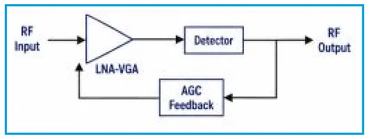
Application: Found in virtually all RF receivers to maximize Receiver Dynamic Range. It ensures that the signal presented to the analog to digital converter (ADC) is always at an optimal, constant level, whether you are standing right next to a Wi-Fi router or are on the edge of its range.
- More deeper understanding, refer AGC Control Algorithm
Phase-Locked Loop (PLL)
Working Operation: A PLL is a feedback system used to generate a highly stable, programmable frequency. A Voltage Controlled Oscillator (VCO) generates an RF output. This output is divided down and compared to a very stable, low frequency reference clock (like a crystal oscillator) in a Phase Frequency Detector (PFD). If the VCO’s phase/frequency starts to drift away from the reference, the PFD generates an error voltage. This voltage is filtered and applied back to the VCO to pull its frequency perfectly in line with the reference.
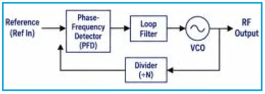
Application: Used as a Frequency Synthesizer in almost all modern radios, cell phones, and test equipment. It allows a radio to tune to specific, precise channels using one single, stable reference crystal.
IQ / DC Offset Calibration
Working Operation: Modern radios often use “direct conversion” architectures to save space and cost, but these suffer from hardware imperfections like DC offset (carrier leakage) and IQ imbalance (mismatch between the In-phase and Quadrature signal paths). This closed loop system samples the RF output, measures these specific errors, and feeds a digital correction signal back to the baseband or modulator stage. It continuously applies digital offsets to perfectly cancel out the analog hardware flaws.
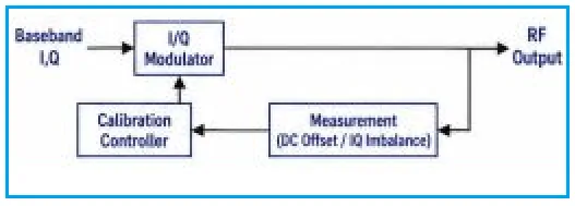
Application: Crucial for Direct Conversion Transceivers found in smartphones, Wi-Fi chips, and Bluetooth devices. It ensures high signal quality (low Error Vector Magnitude) without needing expensive, perfectly matched analog components.
Digital Pre-Distortion (DPD)
Working Operation: RF Power Amplifiers (PAs) are most electrically efficient when driven near their maximum capacity, but doing so causes non-linear distortion (messing up the signal and causing interference to adjacent channels). DPD solves this. A coupler feeds the distorted output back to a digital processor. The processor compares this distorted output to the original, clean input signal. It then calculates an “inverse” distortion algorithm and applies it to the input signal before it reaches the PA. When this intentionally pre-distorted signal hits the non-linear PA, the two distortions perfectly cancel each other out, resulting in a clean output.
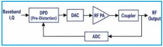
Application: Vital for Linearized RF Power Amplifiers in 4G and 5G cellular base stations. It allows network operators to run their amplifiers at high efficiency (saving massive amounts of electricity) while strictly maintaining signal integrity and regulatory compliance.
Adaptive Beamforming
Working Operation: This is a complex, multi element control loop used in phased array antennas. The system continuously receives signals and analyzes the RF environment (Channel Estimation). A controller calculates specific phase and amplitude “weights” for each individual antenna element in the array. By constantly adjusting these weights based on real time feedback, the system can electronically steer a beam of RF energy directly at a moving user while simultaneously placing “nulls” (areas of zero energy) in the direction of interfering signals.
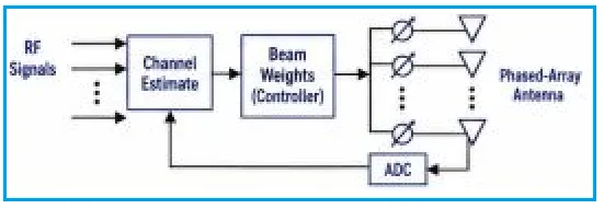
Application: The backbone of Phased Array Radar and 5G/6G Massive MIMO networks. It allows base stations to serve multiple users simultaneously on the same frequency by dynamically focusing distinct spatial beams, vastly increasing network capacity and range.