
Explain Phase Noise to Jitter Conversion : Formula and Calculator
Advertisement
Phase noise to jitter conversion is the mathematical process of translating frequency domain signal instability into time domain timing fluctuations. By integrating the phase noise profile over a specific bandwidth using a standard formula, engineers can calculate the root mean square (RMS) jitter. Utilizing an online conversion calculator simplifies this process, ensuring precise timing analysis in high speed digital and RF circuits.
Phase noise and jitter are critical parameters in frequency domain systems, impacting signal integrity. Converting between the two requires precise formulas and calculations. This guide provides an in-depth explanation of phase noise, jitter, their relationship, and a handy conversion calculator for accurate analysis.
What is Phase Noise
Phase noise is a measure of the spectral purity of crystal oscillators or synthesizers. Ideally, an oscillator should concentrate all its energy at the desired operating frequency when viewed on a spectrum analyzer. However, in practice, oscillators produce phase-modulated noise sidebands in close proximity to the carrier frequency. These small noise sidebands give rise to the concept of phase noise. A common crystal oscillator is the 10 MHz OCXO from Vectron International.
Phase Noise Measurement
There are various methods for phase noise measurements. One method using a spectrum analyzer is depicted in Figure 1. As shown, phase noise is measured very near to the carrier at offsets like 10Hz, 100Hz, 1KHz, 10KHz, and 100KHz. Phase noise represents the difference in level between the peak of the carrier and the magnitude at a specific frequency offset, such as 1KHz. To obtain the final phase noise value, you must add to the difference obtained earlier.
If sidebands are not visible, D is the difference between the peak of the carrier and the noise level at the desired offset frequency.
- RF phase noise measurement setup:
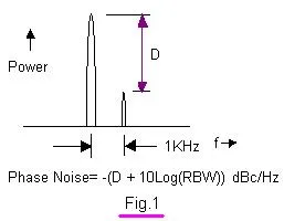 Image alt: rf-phase-noise-measurement
What is Phase Jitter
The time-domain representation of phase noise is phase jitter, which is measured in radians (rms) or picoseconds (rms). Variations in the period or cycle of the time-domain waveform are the primary cause of jitter. This can be attributed to factors like power supply noise, electromagnetic radiation, and interference from other sources.
There are various types of jitter, including absolute jitter and cycle-to-cycle jitter. The difference between the measured and ideal cycle of the time-domain waveform yields cycle-to-cycle jitter. Phase jitter can cause signal shifts in the horizontal axis, leading to Intersymbol Interference (ISI).
Phase Jitter Measurement
- Refer to Application Note AN3359 from Maxim Integrated for a detailed phase jitter measurement method.
Phase Noise to Jitter Conversion Formula
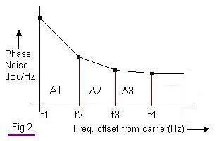 Image alt: phase noise jitter conversion
As shown in the figure, first, the integrated phase noise is derived from to . Let’s denote this integrated phase noise as A. From this integrated phase noise, the RMS phase jitter is obtained using the following equations:
Phase jitter (radians):
Phase jitter (seconds):
Here, is the carrier frequency of the oscillator/synthesizer for which we are finding the phase noise/phase jitter.
Example Calculation : Phase Jitter from Phase Noise
Let’s assume we have broadband phase noise of about -120 dBc/Hz from 1 KHz to 1 MHz, and the oscillator frequency is 10 MHz.
Integrated phase noise () = -120 + 10 () = -120dBc + 70dB = -50dBc
RMS phase jitter (radian), radians
RMS phase jitter (seconds) =
Phase Noise/Jitter Reduction Techniques
- Use filter and bypass capacitors: These eliminate low-frequency power supply noise and high-frequency surges, respectively.
- Follow proper PCB layout design rules: Ensure proper crystal/synthesizer mounting, avoiding long traces, and keeping power and ground signals nearby.
- Use ferrite beads in the circuit.
- Shield the crystal oscillator: This helps eliminate electromagnetic radiation effects.
- Use a highly stabilized power supply: Ensure the power supply has minimal ripple as a power source for the oscillator.
- Use a shield box: Cover the oscillator with a shield box, if space allows.
- Implement a cooling mechanism: Use a heat sink or fan for cooling.
Online Calculators for Phase Noise to Jitter Conversion
Conclusion
Converting phase noise to jitter is crucial for diagnosing signal integrity issues and ensuring accurate timing in high speed communication links. Leveraging exact mathematical formulas and automated calculators streamlines system validation for modern RF engineers.
Explore Phase Noise & Jitter
Explore Calculators on AM-PM, Phase Noise & Harmonics
- RF Phase Noise to Phase Jitter Converter (Calculator)
- RF AM to PM Conversion Calculator
- THD (Total Harmonic Distortion) Calculator
- RF Harmonics Calculator and Formula