
USB Type-C: Features, Specifications, and Pin Diagrams
Advertisement
This article outlines the features and specifications of the USB Type-C interface, including the pin diagrams for both the receptacle and plug. USB has become a ubiquitous interface, replacing older serial and parallel connections in numerous devices. Major players like Apple and Google have embraced USB Type-C connectors and cables in many of their products.
- The USB Type-C design, as discussed here, aligns with USB revision 3.1.
- It boasts a data transfer speed of up to 10Gbps.
- It can handle a maximum power output of 20V/5A.
- Power delivery is bi-directional, offering flexibility in charging.
- It’s commonly found in devices like tablets, smartphones, and laptops.
- It maintains backward compatibility with USB 2.0 LS/FS/HS capabilities.
- It incorporates features to mitigate EMI/RFI (Electromagnetic Interference/Radio-Frequency Interference).
The features of USB Type-C are particularly well-suited for compact, power-hungry smartphones. The standard is managed under the USB PD (Power Delivery) specification. USB PD oversees power delivery and functionalities over USB Type-C connectors and cables.
USB Type-C interfaces are broadly categorized as:
- USB Type-C Receptacle
- USB Type-C Plug
USB Type-C Receptacle Pin Diagram
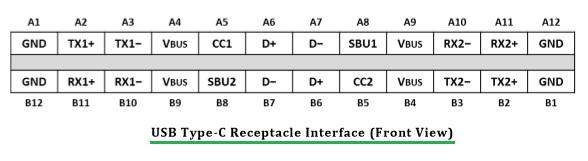
Figure-1: USB Type-C Receptacle pins
The following table details the signals present on the USB Type-C receptacle pins:
| PIN (Signal Name) | Description | PIN (Signal Name) | Description |
|---|---|---|---|
| A1 (GND) | Ground Return | B12 (GND) | Ground Return |
| A2 (SSTXp1) | Positive Half of first superspeed Tx differential pair | B11 (SSRXp1) | Positive Half of first superspeed Rx differential pair |
| A3 (SSTXn1) | Negative half of first superspeed Tx differential pair | B10 (SSRXn1) | Negative half of first superspeed Rx differential pair |
| A4 (VBUS) | Bus power | B9 (VBUS) | Bus Power |
| A5 (CC1) | Configuration Channel | B8 (SBU2) | Sideband Use |
| A6 (Dp1) | Positive Half of the USB 2.0 Differential Pair-Position-1 | B7 (Dn2) | Negative Half of the USB 2.0 Differential Pair-Position-2 |
| A7 (Dn1) | Negative Half of the USB 2.0 Differential Pair-Position-1 | B6 (Dp2) | Positive Half of the USB 2.0 Differential Pair-Position-2 |
| A8 (SBU1) | SideBand Use | B5 (CC2) | Configuration Channel |
| A9 (VBUS) | Bus Power | B4 (VBUS) | Bus Power |
| A10 (SSRXn2) | Negative Half of second superspeed Rx differential pair | B3 (SSTXn2) | Negative Half of second superspeed Tx differential pair |
| A11 (SSRXp2) | Positive Half of second superspeed Rx differential pair | B2 (SSTXp2) | Positive Half of second superspeed Tx differential pair |
| A12 (GND) | Ground Return | B1 (GND) | Ground Return |
The USB PD specification employs BFSK (Binary Frequency Shift Keying) on the VBUS pins and uses the BMC (Bi-phase Mark Coding) protocol on the CC signal line. USB PD version 2.0 defines these functionalities, along with a protocol for negotiating high power with the port partner. It also supports alternate modes such as DisplayPort and MHL (Mobile High-Definition Link) over USB Type-C signals.
USB Type-C devices are categorized into:
- USB Type-C Device: Supports up to 5V/3A.
- USB Type-C Device with PD capabilities: Supports 20V/5A operations and multiple interfaces using alternate modes.
USB Type-C Plug Pin Diagram
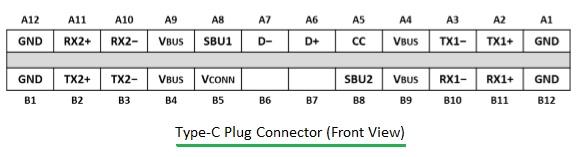
Figure-2: USB Type-C Plug pins
Advertisement


