NFC Squared PCB Antenna Calculator: Modified Wheeler Formula
Advertisement
This page describes an NFC antenna calculator specifically designed for squared PCB antennas to calculate the inductance and total capacitance of an NFC squared PCB antenna using the modified Wheeler formula based on ST Application note.
NFC Antenna Calculator and Example
Here’s an example demonstrating how to use the NFC squared PCB antenna calculator:
INPUTS:
- Number of Squared Antenna Turns, N = 4
- Outer Diameter, in mm = 50 mm
- Inner Diameter, in mm = 30 mm
- K1 as per table below = 2.34
- K2 as per table below= 2.75
- NFC Desired Frequency, MHz = 13.56 MHz
OUTPUTS:
- Inductance = 1.18 µH
- Required Capacitance for Resonance at Desired Frequency = 116.5 pF
Note: User can adjust the input parameters such as number of turns, dimensions and K1/K2 values to achieve the desired inductance and capacitance for their specific NFC application as well as resonance frequency.
NFC Squared Antenna Design
Following is an image of an NFC squared antenna design, which can be used as a reference when designing your own NFC squared antenna using the calculator above. There are two steps to design an NFC squared antenna:
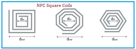 Image Courtesy: ST Microelectronics
| Layout | K1 Value | K2 Value |
|---|---|---|
| Square (left most) | 2.34 | 2.75 |
| Octagonal (Center) | 2.25 | 3.55 |
| Hexagonal (right most) | 2.33 | 3.82 |
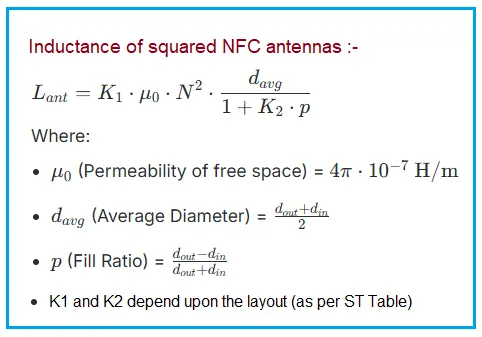
Formulas Used in the NFC Squared Antenna Calculator
- The following formulas are used in this NFC squared antenna calculator. These formulas are based on the design of squared loop antennas and are used to calculate the inductance and capacitance of the antenna based on its physical dimensions and desired resonant frequency.
-
Step-1 : Calculate the inductance of the NFC squared antenna using the modified Wheeler formula:
-
Step-2 : Use the calculated inductance to determine the required capacitance for resonance at the desired frequency using the formula: C = 1 / (4 . π^2 . f^2 . L), where f is the desired resonant frequency and L is the calculated inductance.
References
- AN2866 Application note: “Inductance calculation of NFC squared PCB antennas using the modified Wheeler formula” by ST Microelectronics. Available at: https://www.st.com/resource/en/application_note/an2866-inductance-calculation-of-nfc-squared-pcb-antennas-using-the-modified-wheeler-formula-stmicroelectronics.pdf