
GFP-T vs. GFP-F: Understanding the Differences
Advertisement
This article compares GFP-T and GFP-F modes, explaining the key differences between them. GFP stands for Generic Framing Procedure, and these modes are used to carry client data within GFP frames.
GFP-F is generally used for most packet data types, while GFP-T is typically used for 8B/10B coded signals.
GFP-F Mode
- GFP-F maps each client frame into a single GFP frame.
- GFP-F (Frame-Mapped GFP) is used when the client signal is already framed or packetized by the client protocol.
- It’s well-suited for PDU-based protocols like Ethernet, IP, MPLS, or HDLC-based protocols such as PPP.
- The client PDU is placed directly into the GFP payload field.
GFP-T Mode
- GFP-T allows mapping multiple 8B/10B block-coded client data streams into an efficient 64B/65B block code for transport within a GFP frame.
- GFP-T stands for Transparent GFP.
- It’s suitable for protocols that directly leverage physical layer capabilities.
- GFP-T is transparent to codes like 8B/10B, GbE, FICON, ESCON, DVB, etc.
- GFP-T doesn’t necessarily require the entire PDU to be received.
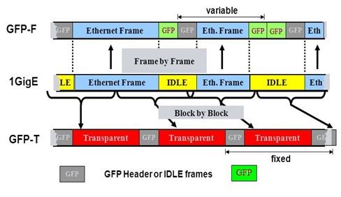
Figure 1 depicts GFP-F and GFP-T frame structures.
GFP-T vs. GFP-F: A Detailed Comparison
The following table highlights the key differences between GFP-T and GFP-F modes:
| Specifications | GFP-T | GFP-F |
|---|---|---|
| Full form | Transparent GFP | Frame-mapped GFP |
| Function | Maps bytes to SONET frames | Maps frames (e.g., Ethernet) to SONET frames |
| Protocol transparency | High | Low |
| Efficiency | Low | High |
| Encapsulation protocol level | Layer-1 (PHY) | Layer-2 (PDU) |
| Isocronic or delay sensitive | YES | NO |
| Optimized for | SAN, DVB | Ethernet |
| Statistical multiplexing of several client signals | NO | YES |
| SAN transport | YES | NO |
| Ethernet transport | POSSIBLE | OPTIMUM |
Tags
Advertisement


