
IMD vs IP3 vs OIP3: RF Linearity Parameters Explained
Advertisement
Intermodulation Distortion (IMD), Third Order Intercept Point (IP3), and Output Third Order Intercept Point (OIP3) are important RF parameters used to evaluate amplifier and receiver linearity. These measurements determine how well an RF device handles multiple signals without generating unwanted distortion products. Understanding IMD, IP3, and OIP3 is essential for designing high performance wireless communication systems, radar equipment, satellite links and RF test instruments.
When dealing with Radio Frequency (RF) amplifiers, the goal is always perfectly linear amplification. We want the output signal to be an exact, larger replica of the input signal. However, in the real world, no amplifier is perfectly linear. When we push multiple signals through an amplifier, its inherent nonlinearity creates unwanted signals. To evaluate how well an amplifier handles this problem, engineers look at IMD, IP3 and OIP3 specifications.
What is IMD (Intermodulation Distortion) ?
It is the unwanted interference generated within a system when two or more distinct frequencies are amplified simultaneously by a nonlinear device.
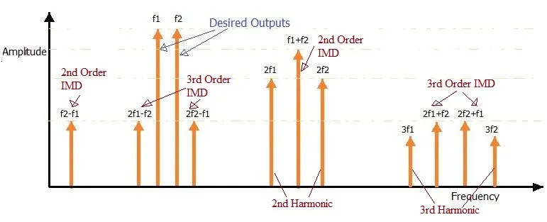
When we input two clean signals (f1, f2) into an amplifier. A perfectly linear amplifier will only output larger versions of f1 and f2. A real world non-linear amplifier, however will mix these signals together and outputs f1, f2 and other spurious signals (e.g. f1+f2, f1-f2, 2f1, 2f2 etc.).
The most problematic of these unwanted signals are the Third-Order Intermodulation Products (IMD3). These occur at frequencies calculated as 2f1-f2 and 2f2-f1. These IMD3 products are extremely close to your original desired frequencies (f1 and f2). Hence they are very difficult to be removed using standard bandpass filters. They degrade signal quality and causes dropped calls in telecom.
What is IP3?
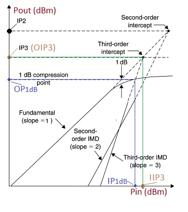
IP3 is the metric used to judge how well an amplifier resists IMD problem. IP3 (Third Order Intercept Point) is a purely theoretical point on graph and is measured as follows.
- Step-1 : Increase the input power of desired signals such that output power increases linearly (i.e. 1:1 ratio).
- Step-2 : At this time, unwanted IMD3 products grow much faster, usually cubically (i.e. 3:1 ratio).
- Step-3 : If we draw two lines on a graph (Output power vs Input power) and extrapolate them, they will eventually intersect. This point of intersection is IP3.
Rule of Thumb : The higher the IP3 value, the more linear the amplifier. An amplifier with a high IP3 will generate significantly lower IMD3 distortion at a given output power compared to one with a lower IP3.
IIP3 vs. OIP3
“IP3” is a general term. When you look at an amplifier datasheet, the manufacturer needs to specify where they are referencing that theoretical intercept point; at the input of the amplifier, or at the output. Based on this, there are two useful terms viz. IIP3 and OIP3.
-
IIP3 (Input IP3): This is the Third Order Intercept Point referenced to the input power. It essentially measures the amplifier’s linearity without factoring in its gain. It is measured in unit of dBm.
-
OIP3 (Output IP3): This is the Intercept Point referenced to the output power. Because it represents the final amplified signal that travels down the line, OIP3 is the specification most commonly cited on amplifier datasheets. It is also measured in dBm.
Relationship between IIP3 and OIP3
Because the only difference between the input and the output of the amplifier is the gain, the mathematical relationship between IIP3 and OIP3 is straightforward addition.
Summary
IMD quantifies distortion, while IP3 and OIP3 estimate the linearity limit of RF devices. Higher IP3 values generally indicate better amplifier performance and improved signal integrity. As we know nonlinearity causes IMD and hence to guarantee a clean signal, you must select an amplifier with a high OIP3, which guarantees lower distortion and better overall performance.
Continue Learning Non-Linearity, Intercept Points & P1dB (IP3, TOI, PIM)
Start here to understand how RF amplifiers and mixers behave when pushed into compression, and how engineers measure intermodulation distortion (IMD).
- Understanding P1dB and TOI (Third-Order Intercept)
- Difference Between IMD, IP3, and OIP3
- IP2 and IP3 Formulas, Calculations, and Significance
- Passive Intermodulation Distortion (PIM): Causes & Mitigation
- Cross-Modulation vs Intermodulation