
QFH Antenna Basics and Calculator
Advertisement
This page covers QFH Antenna basics and provides a QFH antenna calculator and its formula. QFH stands for Quadrifilar Helix or Quadrifilar helicoidal. This calculator is useful to design Quadrifilar Helix or Quadrifilar helicoidal Antenna.
A QFH antenna calculator does following.
- Converts frequency into wavelength
- Uses wavelength based formulas
- Outputs precise antenna dimensions
- Ensures optimal circular polarization and coverage
QFH Antenna Calculator
INPUTS:
- Frequency = 137.5 MHz
- Number of Turns (Twist) = 0.5
- Length of one turn (in wavelengths)= 1
- Bending Radius = 15 mm
- Conductor Diameter = 7 mm
- Width/Height Ratio = 0.44
OUTPUTS:
Generic (Common):
- Wavelength = 2181.8 mm
- Compensated Wavelength = 2336.7 mm
- Bending Correction = 6.4 mm
Larger Loop:
- Total Length = 2397.4 mm
- Vertical separator = 889.6 mm
- Total Compensated Length = 2423.2 mm
- Compensated Vertical Separation = 859.6 mm
- Antenna Height (H1) = 731.8 mm
- Internal Diameter (Di1) = 315 mm
- Horizontal Separator (D1) = 322 mm
- Compensated Horiz. Separation (Dc1) = 292 mm
Smaller Loop:
- Total Length = 2278.3 mm
- Vertical tube = 845. 8 mm
- Total Compensated Length = 2304 mm
- Compensated Vertical tube = 815.8 mm
- Antenna Height (H2) = 695.8 mm
- Internal Diameter (Di2) = 299.1 mm
- Horizontal Separator (D2) = 306.1 mm
- Compensated Horiz. Separation (Dc2) = 276.1 mm
Assumption : Length of one turn : 1 wavelength
- A few variations of the antenna exist. Normally the circumference (length of the loop) is 1 wavelength, but 1.5 wavelength and 2 wavelength versions exist.
QFH Antenna Calculation
The QFH antenna is one of various antennas used to capture images from low level, non-geosynchronous satellites. It is a very simple, effective and efficient antenna. It doesn’t have null spots directly overhead or at other inopportune locations like some other antennas. It’s also a popular antenna used for GPS applications.
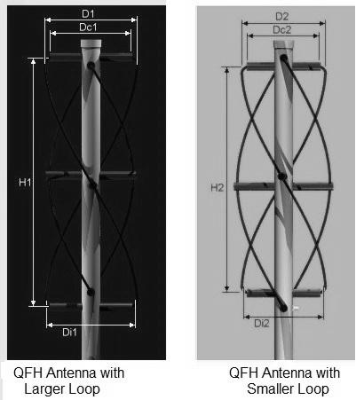
The QFH antenna design consists of two types of loops. This helps in noise reduction and elimination of null spots. Figure 1 (not included here, but imagine one!) depicts a typical QFH antenna designed with a larger loop and a smaller loop. PVC pipe, copper wires or thin tubing, coaxial cable and BNC connectors are commonly used in its construction.
Applications/Benefits
A QFH (Quadrifilar Helix) antenna is a circularly polarized antenna made of four helical conductors arranged symmetrically around a central axis. It is widely used for following.
- Satellite communication
- Weather satellite reception (NOAA, METEOR, etc.)
- GNSS and space telemetry
- VHF/UHF omnidirectional applications
The QFH antenna is especially valued because it provides following features and benefits.
- Right Hand or Left Hand Circular Polarization (RHCP/LHCP)
- Near hemispherical radiation pattern
- Excellent overhead coverage
Summary: QFH Calculator is an indispensable tool for satellite reception, RF experimentation and antenna design projects.
References for further study
- A Novel Feeding Technique for a Quadrifilar Helix Antenna : Recent research on phasing and feed design for QFH antennas.
- Design of a Self Phased Quadrifilar Helix Antenna for Satellite Communication : Case study on QFH for telemetry with experimental radiation patterns.
- Kilgus, C.C. — Resonant Quadrifilar Helix Design Book ; One of the early classic references on QFH antenna theory and design (Microwave Journal)
- jcoppens.com QFH Calculator : Free online calculator used in many QFH design discussions (often referenced by builder communities) ((https://jcoppens.com/ant/qfh/calc.en.php))
Advertisement


