
Antenna Testing in EMI/EMC Chambers: Steps & Measurements
Advertisement
Introduction : Testing is crucial before a product enters the real world to ensure it works reliably, has good range, and complies with strict global regulatory standards (like FCC, IEC, or CISPR). Antenna testing in an EMI EMC chamber is performed to evaluate antenna radiation characteristics, electromagnetic compatibility, and RF performance under controlled conditions. Measurements such as radiation pattern, antenna gain, directivity, polarization, efficiency, and electromagnetic emissions can be performed using suitable test antennas, receivers, positioners, and calibrated measurement equipment.
What is an EMI/EMC Chamber?
An Electromagnetic Interference (EMI) / Electromagnetic Compatibility (EMC) chamber is a specialized, highly controlled testing environment. It is a shielded room designed to block out all external electromagnetic signals (like radio stations, cell towers, or Wi-Fi).
The interior walls are lined with anechoic absorbers (often in cone shaped foam) that absorb internal radio waves, preventing them from bouncing off the walls and creating echoes or reflections.
This creates a quiet environment, allowing engineers to measure the true performance of an antenna without outside environment.
Antenna Testing Process
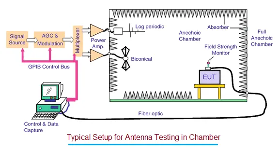
The typical testing setup involves placing the Antenna Under Test (AUT) inside the chamber on a rotating turntable. A stationary Reference Antenna (or Test Antenna) is also placed in the chamber to transmit or receive signals. These are connected to external computers and Measurement Receivers/Spectrum Analyzers located outside the shielded door.
Step 1: Before placing the device in the chamber, engineers must define the specific objectives of the test ( i.e. gain, pattern, or efficiency measurements). They select the required frequency range for the specific device, ensure all testing instruments are fully calibrated, and verify that the chamber conditions are optimal.
Step 2: After physical connections are mad, the reference antenna is connected to the positioner and the external receiver equipment. It is vital to ensure that all cabling is proper and that necessary power or signal line filters are in place to prevent interference from traveling along the wires into the chamber.
Step 3: Because cables, connectors, and the testing equipment itself can slightly alter the signal, the system must be calibrated. Engineers run a baseline test using a known, perfectly characterized reference antenna. This allows the software to “normalize” the system, mathematically removing any system errors or cable losses so that only the performance of the AUT is measured later.
Step 4: The device being tested (the AUT) is securely mounted onto the non-conductive turntable inside the chamber. It is connected using high quality, low loss cables. Crucially, these cables must be routed carefully to ensure they do not interfere with the antenna’s radiation path.
Step 5: Using software on an external PC, the engineers configure the Measurement Receiver or Spectrum Analyzer. They set the specific frequency range (start and stop points), define the Resolution Bandwidth (RBW), choose the detector type and set the sweep time based on the specific standards they are testing against.
Step 6: The automated testing begins. The turntable rotates the AUT slowly in a full circle (Azimuth 0 to 360 degrees). Depending on the setup, the positioner may also alter the height or angle (Elevation) of the antenna. As the AUT moves, the measurement receiver continuously records the signal strength at every position, building a complete profile of how the antenna transmits or receives energy in all directions.
Typical Antenna Measurements
-
Radiation Pattern (2D / 3D): A visual map showing the shape of the electromagnetic energy emitted by the antenna. It shows where the signal is strongest and where there are dead zones.
-
Antenna Gain: Measures how well the antenna concentrates its radiated power in a specific direction compared to a standard, theoretical antenna.
-
Efficiency: The ratio of the total power radiated by the antenna compared to the electrical power fed into it (how much energy is successfully converted into radio waves versus lost as heat).
-
Directivity: Similar to gain, this measures the concentration of the radiation pattern in its strongest direction, regardless of the antenna’s electrical efficiency.
-
Return Loss (VSWR): Measures impedance matching. It shows how much of the signal is reflected back to the transmitter instead of being radiated out. A lower reflection indicates a better-tuned antenna.
-
Beamwidth: The angle or width of the main lobe of the radiation pattern where the signal is strongest.
-
Polarization: The physical orientation of the electromagnetic wave created by the antenna (e.g.vertical, horizontal, or circular).
Summary
Antenna testing in an EMI/EMC chamber provides controlled measurements of radiation and electromagnetic performance. These comprehensive tests ensure that antennas used in everyday applications from wireless IoT devices and 5G smartphones to complex automotive radars and satellite communications perform efficiently and safely.
Continue Learning EMI/EMC Fundamentals & Standards
Mitigation, Shielding & Hardware Components
- Understanding the Purpose of EMI Filters
- EMI Filter Circuit Design and Operation
- EMI Shielding: Metal Braid vs Aramid Fiber
- EMC Bonding Types and Behavior in RF/Microwave
- EMC Thermopad Attenuator (App Note)