
Radiated Emissions: Measurements & How to Overcome Them
Advertisement
Radiated emissions are unwanted electromagnetic energy emitted from electronic equipment, cables, circuit boards, enclosures, or other components that can interfere with nearby electronic systems. Radiated emission testing is an important part of electromagnetic compatibility (EMC) compliance and is typically performed using calibrated antennas, EMI receivers or spectrum analyzers, and an EMI/EMC test chamber or open area test site. This article explains what radiated emissions are, their common sources, measurement methods, applicable EMC considerations, and practical techniques to reduce excessive emissions.
What are radiated emissions
Every electronic device, from the smartwatch on your wrist to the complex servers running the internet, shares a common, invisible side effect: they all generate electromagnetic energy. While these devices are designed to perform specific functions, the internal currents and voltages required to make them work inevitably leak outward into free space. In the realm of Electromagnetic Interference (EMI) and Electromagnetic Compatibility (EMC), these leaked signals are known as Radiated Emissions.
How Radiated Emissions Affect Other Systems
When a device (often referred to as Equipment Under Test or EUT) acts as an unintentional transmitter, the consequences for surrounding electronics can range from mild annoyance to catastrophic failure.
-
Communication Interference: This is the most common symptom. Unwanted RF energy can raise the “noise floor” in an environment, degrading the performance of intentional wireless systems like Wi-Fi routers, Bluetooth devices, and GPS (GNSS) receivers.
-
Circuit Malfunctions: If a sensitive electronic circuit acts as an unintentional receiver for these emissions, the induced voltages can cause the system to behave erratically. This manifests as random resets, system lockups, corrupted data streams, or unintended operations.
-
Regulatory Non-Compliance: To prevent electronic chaos, government and international bodies (like the FCC in the US or CISPR globally) enforce strict limits on how much energy a device is legally allowed to radiate. Failing to meet these standards means a product cannot be legally sold.
-
Reduced Reliability: Devices that constantly battle internal or external interference suffer from reduced product reliability, leading to increased field failures and customer complaints.
Measurement Setup
Testing usually occurs in a specialized EMI chamber or an Open Area Test Site (OATS). The standard setup involves placing the EUT on a non-conductive turntable that rotates 360 degrees. A measurement antenna is placed at a specific distance of about 3 or 10 meters away. It is attached to an adjustable mast that can vary its height (usually between 1 and 4 meters).
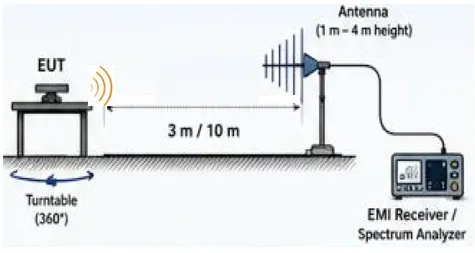
As emissions radiate in complex patterns, the turntable and the variable-height antenna are used together to find the “worst-case scenario” angle and elevation.
Emissions behave differently depending on their frequency, requiring engineers to use specific antennas to capture different components of the electromagnetic field. For this task loop antenna and horn antennas are used. Loop antennas are used primarily for frequencies below 30 MHz (typically 9 kHz to 30 MHz) and measures H-field. Horn antennas are used for higher frequencies, ranging from 200 MHz up into the microwave range (40 GHz and beyond). Horn antennas measure electric field (E-field) component of the emission.
How to Overcome Radiated Emissions
Following are the primary strategies to overcome radiated emissions.
-
Good PCB Design (The First Line of Defense) : The most effective way to stop emissions is to prevent them from generating in the first place. This means minimizing “loop areas” on the circuit board where current travels out and returns. Designing PCBs with short signal traces, proper return paths, and continuous, solid ground planes significantly reduces the board’s tendency to radiate energy.
-
Utilizing Filters and Ferrites : When high frequency noise is unavoidable, it must be suppressed before it reaches cables or escapes the board. Engineers use low pass filters and ferrite beads on power lines, signal lines, and Input/Output (I/O) ports to choke off high frequency spikes while letting the intended lower frequency signals pass through.
-
Effective Shielding : If the PCB design cannot contain all the noise, physical barriers are required. Using metal enclosures, shielded cans placed directly over noisy components, or conductive coatings applied to the inside of plastic housings will block or heavily attenuate the escaping electromagnetic waves.
-
Cable Management : Cables are the most common unintentional antennas in any system. Mitigating cable emissions involves keeping cables as short as possible, using twisted pair wiring (which helps cancel out magnetic fields), utilizing shielded cables, and ensuring proper routing away from noisy components on the board.
-
Proper Grounding : A robust grounding strategy prevents the buildup of noise voltages. Ensuring low impedance connections and avoiding ground loops (where multiple paths to ground create a large, radiating loop antenna) is critical for system stability.
Summary
Radiated emissions are unwanted electromagnetic signals that can cause interference and EMC compliance problems. They can be mitigated using methods such as proper PCB layout, grounding, shielding, filtering, cable management, suppression components, ferrite beads, and careful enclosure design.