RC Phase Shift Oscillator Using BJT, FET & Op-Amp Explained
Advertisement
Introduction : A 3-stage RC Phase Shift Oscillator is an electronic oscillator circuit that generates sinusoidal waveforms using a resistor capacitor (RC) feedback network and an amplifying device such as a BJT, FET or operational amplifier. It is widely used for generating low frequency sine waves (audio frequency range).
3-Stage RC Phase Shift Oscillator
For sustained oscillations, an oscillator must satisfy the Barkhausen Criterion conditions as follows.
- Total phase shift around the loop = 360 degrees (or 0 degrees)
- Loop gain > = 1
In a 3-stage RC phase shift oscillator:
-
Each RC section provides 60 degree phase shift
-
Three RC sections provide 180 degree total phase shift
-
The amplifier provides the remaining 180 degree phase shift
-
Hence, 180 + 180 = 360 degrees. Tbis satisfies the oscillation condition.
Frequency of oscillation can be expressed as follows.
Where,
-
f = Frequency of oscillation
-
R = Resistance
-
C = Capacitance
-
Minimum Amplifier gain required is Av >= 29.
Circuit Types of RC Phase Shift Oscillator
The oscillator can be implemented using three types of amplifiers:
- BJT RC Phase Shift Oscillator
- FET RC Phase Shift Oscillator
- Op-Amp RC Phase Shift Oscillator
BJT RC Phase Shift Oscillator
In this circuit, the amplifier is a Bipolar Junction Transistor operating in common-emitter configuration The collector output is fed back to the base through three RC networks.
The components include transistor amplifier, three RC sections, biasing resistors and coupling capacitor.
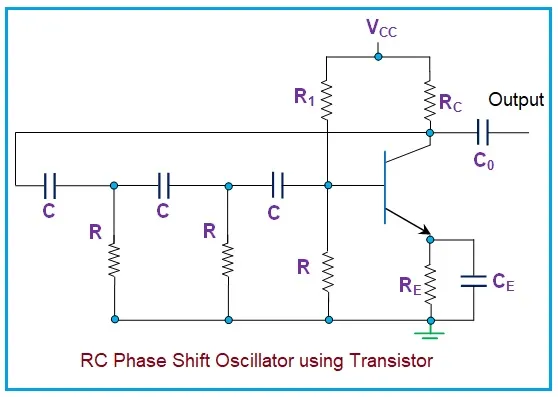
Following steps explain its working.
- When power is applied, small noise signals appear in the circuit.
- The transistor amplifies these signals.
- The output signal passes through the three RC networks, which produce 180° phase shift.
- The common-emitter transistor amplifier adds another 180° phase shift.
- The total phase shift becomes 360 degree, causing the signal to reinforce itself.
- The circuit continues producing sustained sinusoidal oscillations.
FET RC Phase Shift Oscillator
This oscillator uses a Field Effect Transistor amplifier.
Key characteristics include high input impedance, RC network connected between drain output and gate input and Usually configured as common source amplifier.
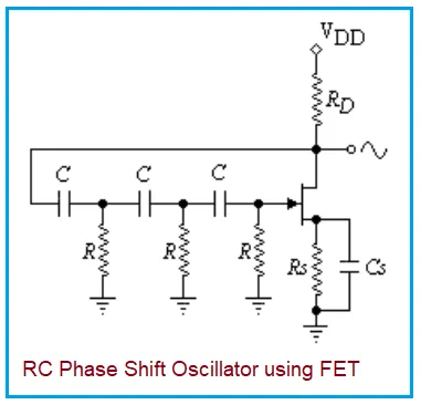
Following steps describe working of this circuit.
- The FET amplifies the input signal.
- The output from the drain passes through the three RC phase shift networks.
- Each stage produces 60° phase shift.
- The total phase shift becomes 180 degree from the RC network.
- The FET amplifier introduces another 180 degree phase shift.
- The feedback signal becomes in phase with the input, maintaining oscillations.
Op-Amp RC Phase Shift Oscillator
This oscillator uses an Operational Amplifier as the amplifier.
The key components include Op-amp in inverting configuration, three RC feedback networks and feedback resistor to set gain.
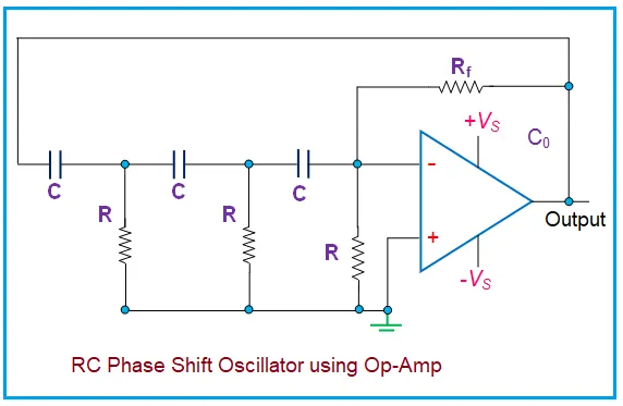
Following steps describe working of op-amp circuit.
- The op-amp amplifies the signal with 180 degree phase inversion.
- The output is passed through the three RC phase shift sections.
- Each RC section introduces 60 degree phase shift, producing 180° total shift.
- The total loop phase shift becomes 360 degree.
- If the gain is >= 29, oscillations start and continue.
Advantages:
Following are benefits of op-amp circuit.
- Simpler circuit design
- No transistor biasing required
- Good stability
- Suitable for low frequency signal generation
Summary
Due to its simple design and ability to generate stable sine waves, the RC phase shift oscillator is widely used in audio signal generators, testing equipment, instrumentation circuits and communication systems.