UWB Radar Tutorial: System and Working Explained
Advertisement
This tutorial delves into the fundamentals of UWB (Ultra-Wideband) radar systems. We will explore the UWB radar system’s basics, including a detailed block diagram illustrating the transmitter and receiver components. Furthermore, we will discuss the advantages and disadvantages of UWB radar compared to conventional radar systems.
What is UWB?
UWB, short for Ultra-Wideband, is a technology that utilizes wide bandwidth signals at low power levels, often below the noise floor. It’s formally defined in the IEEE 802.15.4a specifications. UWB systems operate across three frequency bands: below 1 GHz, 3 to 5 GHz, and 6 to 10 GHz.
UWB signals are generated using very short duration pulses (approximately < 1 ns). Consequently, the frequency spectrum of a UWB signal is considerably wider compared to narrowband systems.
UWB Radar Working Operation
A radar system that employs signals with UWB characteristics is known as a UWB radar. The UWB signal occupies a significantly wider frequency range than conventional radar systems. Additionally, it operates at very low power, often less than the thermal noise signal power.

UWB Transmitter Block Diagram
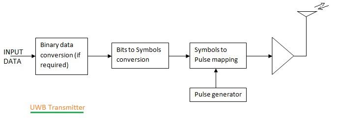
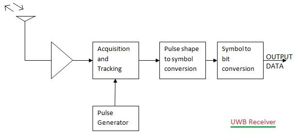
The figure above illustrates a typical UWB transmitter and receiver block diagram.
The UWB transmitter converts the information to be transmitted into pulses, which are then amplified by an amplifier. The amplified signal is subsequently transmitted via an antenna, as shown.
At the receiver, zeros and ones are decoded from the received pulse train based on the time interval between pulses.

UWB Receiver Block Diagram
Bits to symbol conversion is done with the help of modulation scheme.
UWB commonly employs time-based modulation schemes (e.g., PPM - Pulse Position Modulation) and pulse shape-based modulation schemes (e.g., PAM - Pulse Amplitude Modulation, OOK - On-Off Keying, Bi-phase, Orthogonal pulse modulation).
UWB technology finds applications in diverse domains, including asset tracking, military, healthcare, medicine, and networking. Similarly, UWB radars are used for various purposes, such as detecting concealed objects, geographical surveys using airborne systems, infrastructure mapping, and snow thickness measurement.
UWB Radar System Block Diagram

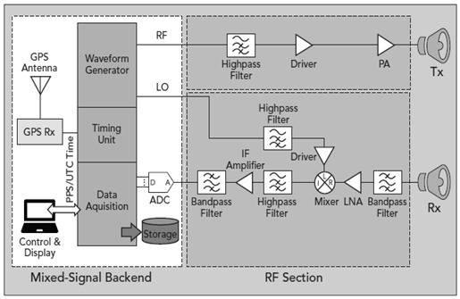
UWB Radar System Block Diagram (Courtesy: MWJOURNAL.COM)
The figure above depicts a typical block diagram of a UWB radar system. The UWB transmitter part consists of a waveform generator, RF filter, driver, power amplifier, and transmit antenna.
The UWB receiver consists of a receiving antenna, RF filter (BPF type), LNA (Low Noise Amplifier), down converter (using a mixer and LO circuit), IF amplifier (to amplify the down-converted IF signal), IF filter (BPF type), and ADC (Analog to Digital Converter).
The digital output of the ADC is acquired and processed to retrieve desired information, tailored to specific applications. A timing unit, along with GPS, aids in synchronization to provide the start of frame.
Like other active radars, UWB radar transmits a frequency-modulated chirp signal in the 2 to 18 GHz range. The waveform generator shown in the diagram can be used to produce this signal. The scattered or reflected signal from the target scene is captured using the receiving antenna. The received RF signal is down-converted to IF and processed to retrieve the desired information with the help of a data acquisition system.
Advantages of UWB Radar
Following are the benefits or advantages of UWB radar system:
- Due to its broad operating bandwidth, UWB radars are capable of resolving closely spaced targets.
- It uses low power and possesses good noise immunity.
- UWB radar uses UWB signals which can penetrate a variety of materials easily. Hence, it can be used for a wide variety of applications.
- It can be used in multipath fading environments due to its higher immunity against such fading.
- Higher data rates (about 1 Gbps) can be achieved using a UWB system.
Disadvantages of UWB Radar
Following are the drawbacks or disadvantages of UWB radar system:
- UWB radar has a longer signal acquisition time.
- It has a slow adoption rate.
- UWB systems have certain co-existence and interference-related issues with other wireless technologies that use similar bands.
Advertisement
 RF
RF


