
RF Receiver Sensitivity Measurement: Test Setup and Procedure
Advertisement
RF receiver sensitivity measurement determines the minimum signal level required for a receiver to demodulate data effectively. This parameter directly impacts the range and performance of RF communication systems. Test setups often include signal generators, attenuators, and BER analyzers for precise measurements. This guide covers the key aspects of receiver sensitivity measurement, tools required, and step-by-step instructions for ensuring accurate results. This test will verify the ability of the RF receiver to function at a minimum power level in addition to meeting the BER (or PER) and other performance requirements as desired.
Test Setup for Receiver Sensitivity Measurement
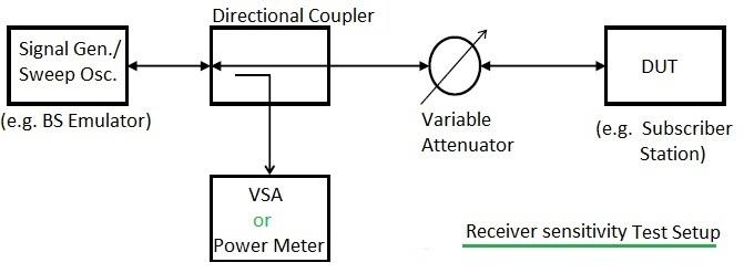
Figure 1: Test setup used for RF Receiver sensitivity measurement.
The following equipment or tools are used for the measurement:
- RF Signal generator or Sweep Oscillator
- Directional Coupler
- VSA (Vector Signal Analyzer) or RF Power Meter
- Variable Attenuator
Sensitivity for a Single Carrier receiver case can be mentioned as follows: -120dBm at a BER of . This is usually specified for example in VSAT RF Transceivers or other RF devices.
Test Procedure for Receiver Sensitivity Measurement
The following test procedure is followed for receiver sensitivity measurement:
- Setup: Do the test setup as shown in Figure 1.
- Signal Generator Configuration: Set the desired signal frequency and power in the signal generator.
- BER Measurement: Measure the BER in the VSA or use a BER setup if the feature is not available in the VSA.
- Power Reduction: Reduce the power level in the signal generator or increase the attenuation level in the variable RF attenuator as shown, and go down until the sensitivity level has been reached (say -120 dBm).
- Performance Check: Now check the performance of the DUT (Device Under Test) or note down the BER measurement at this point. A BER of the desired value (Say ) should be achieved in order to conclude that the DUT has passed the receiver sensitivity test.
Sensitivity for OFDM Receiver Case
Sensitivity for OFDM (Orthogonal Frequency-Division Multiplexing) receiver case is specified as follows:
(For no sub-channelization used, .)
The following table mentions different receiver sensitivity values for different modulation types and corresponding SNR values. This is for the fixed WiMAX specification as specified in IEEE 802.16-2004 OFDM Physical layer.
| Burst type (modulation, code rate) | SNR | Receiver sensitivity |
|---|---|---|
| BPSK 1/2 | 6.4 | -83.04 dBm |
| QPSK 1/2 | 9.4 | -80.04 dBm |
| QPSK 3/4 | 11.2 | -78.24 dBm |
| 16QAM 1/2 | 16.4 | -73.04 dBm |
| 16QAM 3/4 | 18.2 | -71.24 dBm |
| 64 QAM 2/3 | 22.7 | -66.74 dBm |
| 64 QAM 3/4 | 24.4 | -65.04 dBm |
According to the table, a different limit for sensitivity is specified for different modulation types, and the same has to be verified to determine the pass/fail criteria in OFDM receiver testing.
Conclusion
Measuring RF receiver sensitivity accurately is essential for optimizing the performance of communication systems. Proper test setups and calibration techniques help ensure reliable measurements and enable engineers to design systems with superior signal detection capabilities. This knowledge is critical for achieving robust and efficient RF designs.
Advertisement


