NFC RF Measurements Chart and Test Setup
Advertisement
This page describes the NFC RF measurements chart and the test setup used for NFC RF measurements. It outlines RF measurements for NFC devices in both polling and listening modes. NFC stands for Near Field Communication and operates on the principle of inductive coupling, similar to a transformer.
The NFC device operates in two modes: polling mode and listening mode. The coil or loop antenna has a rectangular or circular shape. The NFC operating frequency is 13.56 MHz, supporting a maximum data rate of about 424 kbps. Both NFC polling and listening devices operate within a distance of about 10 cm. They can operate in different modes, including card emulation, peer-to-peer, and reader/writer modes.
NFC devices support one or a combination of standards, including NFC-A, NFC-B, and NFC-F.
The table below mentions different modulation schemes, coding rates, and data rates supported in these different NFC standards.
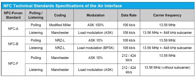
Table 1: NFC standards
ASK modulation with 10% and 100% modulation and BPSK modulation types are used. ASK modulation is also known as load modulation.
The following RF measurements are performed when an NFC device operates in listening mode and polling mode. Tables 2 and 3 list the common NFC test cases. NFC uses various coding techniques such as modified Miller, Manchester, and NRZ-L. These different coding techniques depend on the NFC forum standards, i.e., NFC-A, NFC-B, or NFC-F.
| NFC RF Measurements | Description |
|---|---|
| Carrier frequency accuracy | This test ensures that the NFC carrier frequency does not deviate more than desired. |
| Power level | This test ensures that sufficient power is used in transmit mode (i.e., polling mode). |
| NFC waveform | This test ensures that the NFC timing waveform meets the rise time, fall time, and other parameters as per the mask defined in the standard. |
| Load modulation sensitivity | This test ensures that the Device Under Test (DUT) in polling mode receives load modulation with a minimum specified level. |
| Threshold level | This test ensures that the NFC DUT in polling mode switches off RF when exposed to an external RF field of a certain strength. |
Table 2: NFC RF Measurements in active polling mode
| NFC RF Measurements | Description |
|---|---|
| Load Modulation | The load modulation signal strength should be within the limit when the DUT operates in listening mode. |
| Power reception | The DUT in listening mode will reply properly even in a noisy environment. This ascertains that power reception is proper even in bad conditions. |
| Frame delay time | This test is done when the smartphone is in card emulation mode. It is the time duration from the end of the polling command until the start of the transmission. |
Table 3: NFC RF Measurements in passive listening mode
NFC RF Measurements Test Setup
Polling Mode
NFC RF measurements require a reference polling device and a reference listening device. The reference polling device is used to test the NFC DUT in listening mode. The reference listening device is used to test the NFC DUT in polling mode.
The test setup uses the following NFC equipment and software applications to perform RF and baseband measurements to validate the NFC DUT:
- VSG (Vector Signal Generator): Used to generate polling commands and listener responses.
- VSA (Vector Signal Analyzer) or RF Spectrum Analyzer: Used to analyze or measure waveforms from the NFC DUT.
- Oscilloscope: Used to verify the NFC timing waveform against a defined mask. This validates rise time, fall time, and other timing parameters of the NFC waveform.
- Various baseband applications are developed to provide NFC waveform creation and analysis functionalities according to the NFC standards (A, B, and F).
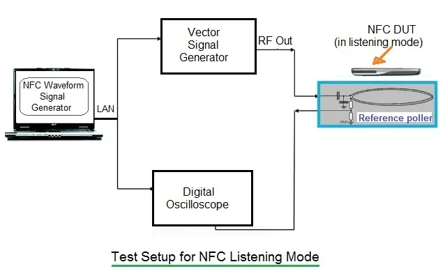
Figure 1: NFC test setup used to test the NFC DUT in passive listening mode.
Listening Mode
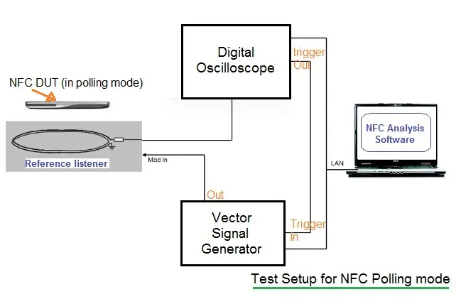
Figure 2: NFC test setup used to test the NFC DUT in active polling mode.
Rohde & Schwarz offers complete solutions for NFC RF measurements, including:
- R&S® SMBV100A VSG (Vector Signal Generator)
- R&S® RTO digital oscilloscope
- R&S® FS-K112PC NFC measurement application software
- R&S® ZVL VNA (Vector Network Analyzer)