
Explain RF Link Budget and Friis Transmission Equation: A Practical Guide
Advertisement
An RF link budget is a comprehensive calculation of all gains and losses in a communication system, ensuring a signal reaches the receiver with sufficient strength. The core of this analysis is the Friis Transmission Equation, which mathematically determines the received power based on transmission power, antenna gains, operational frequency and the distance between the transmitting and receiving antennas.
In wireless communication, signal reliability hinges on efficient link planning. RF link budgets and the Friis transmission equation are indispensable tools for engineers assessing system performance.
Example RF Link Budget for Ku band system
An example of a link budget for a Ku band satellite system in a star topology is provided below. Wireless systems typically consist of various subsystems that introduce gains and losses as the signal propagates from the transmitting end to the receiving end. For example, an amplifier will amplify the signal, while an attenuator, cable, or free space introduces varying degrees of loss. An antenna provides gain. Calculating the different parameters of the RF link to ensure optimal BER (Bit Error Rate) or Eb/N0 (Energy per bit to Noise Power Spectral Density ratio) is often referred to as RF Link Budget.
Essentially, RF engineers determine the required HPA/SSPA (High Power Amplifier/Solid State Power Amplifier) power at the transmitting end, taking into account various system specifications before deployment.
In simple terms, expressed in decibels:
Power at receiver = Power at transmitter + Gains + Losses
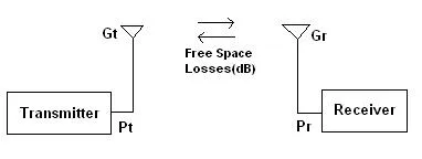
Friis Transmission Equation
The equation is outlined below in linear form:
Where:
- = Transmit power
- = Receive power
- = Transmitter antenna gain
- = Receiver antenna gain
- = Distance between two antennas
In decibel form:
RF Link Budget Calculation for Ku band satellite system
Let’s illustrate the RF link budget with an example of a star configuration-based VSAT (Very Small Aperture Terminal) system utilizing a Ku band satellite. Both VSATs have a diameter of 2.4 meters. Input parameters include information data (information rate, FEC rate, modulation, BER, Eb/N0), satellite data (latitude, longitude, azimuth, elevation), various attenuations, and Earth station data for VSAT1 and VSAT2. Output parameters are (C/N)uplink, (C/N)downlink, (C/N)total, and the required HPA power. The following table lists all these parameters in a typical RF link budget calculation.
- Download excel sheet from RF wireless world web site’s download section.
Summary
Mastering the RF link budget and the Friis Transmission Equation is critical for predicting wireless range and optimizing antenna deployments. Accurate calculations prevent signal dropouts and guarantee highly reliable data links in satellite and terrestrial networks.