
Filter Shape Factor and Bandwidth Explained
Advertisement
The filter shape factor and bandwidth are fundamental metrics in signal filtering. This guide explains their mathematical formulas, derivations, and practical examples, providing a comprehensive understanding of their applications in designing filters.
Shape Factor
-
It indicates the selectivity of the filter.
-
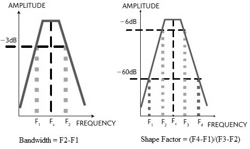
It is the ratio of the filter’s response at 60 dB to the response at 6 dB attenuation, as shown in the figure.
-
The RF Filter shape factor can be expressed by the following equation:
RF Filter Shape Factor =
-
The lower the value of the shape factor, the steeper the response of the RF filter.
Bandwidth
-
The frequency range around the center frequency over which the filter can be used efficiently and effectively is known as the bandwidth.
-
Frequencies above and below the center frequency at which the response falls down by 3 dB with reference to the center frequency indicate the upper and lower limits of the filter bandwidth.
-
The RF Filter Bandwidth can be expressed by the following equation:
Bandwidth =
Here, is the center frequency.
Conclusion
Understanding the filter shape factor and bandwidth formula empowers engineers to design filters that meet specific performance criteria, enhancing overall system efficiency.
Advertisement


