Difference between Power Divider and Power Splitter
Advertisement
Introduction : While the terms “power divider” and “power splitter” are often used interchangeably, they refer to two distinct components with different internal designs and intended applications. Both are passive, resistive circuits used to divide an input signal, but how they manage impedance and signal reflections is fundamentally different.
The Power Divider (Three-Resistor Design)
A power divider is designed to split a single input signal into two or more output signals while maintaining a constant impedance match on all ports.
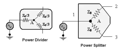
Example design: The most common 2-way power divider uses a three-resistor configuration. Typically, three 16.6 Ohm resistors are arranged in a “star” or “tee” network. This design ensures that if all ports are connected to a 50 Ohm system, the input and both outputs will “see” a perfect 50 Ohm impedance.
Primary Application: Signal Distribution
The main use for a power divider is to distribute a signal to multiple places, such as in a clock fanout. In this scenario, you need to drive two separate components with the same clock signal, and it is critical that the components do not interfere with one another. The impedance matching and good isolation of the power divider are essential for this.
The Power Splitter (Two-Resistor Design)
A power splitter is specifically designed to split an input signal into two outputs in a way that delivers equal incident power to both loads, regardless of whether those loads are matched.
Example Design: A power splitter uses a simpler two resistor configuration. It typically consists of two 50.0 Ohm resistors.
Primary Application: Ratio Measurements
The power splitter is ideal for applications like measuring the gain of a Device Under Test (DUT). The input signal is split, with one path going to the DUT and the other to a reference detector. Because the splitter provides a constant power ratio to its outputs regardless of the DUT’s input impedance, you can get an accurate gain measurement without the DUT’s reflections skewing the results.
Key differences
| Feature | Power Divider (3-Resistor) | Power Splitter (2-Resistor) |
|---|---|---|
| Design | Three resistors e.g. 16.6 Ohm each | Two resistors e.g. 50 Ohm each |
| Impedance matching | All the ports are matched to the system impedance | Only the input port is matched; outputs are not. |
| Isolation between outputs | Good (typically -6 dB). Outputs are isolated. | Poor (typically -12 dB). Outputs are not isolated. |
| Behavior with Mismatched Loads | Reflections from a mismatched load can unbalance the system. | Maintains an equal power ratio to the loads, even if they are mismatched. |
Conclusion: The choice between them is based on application. Use a Power Divider when you need all ports to be perfectly matched and isolated from one another. Use a Power Splitter when you need to maintain a precise power ratio between outputs, especially when driving a device with an unknown or imperfect input match.